. 2024 Jun 5;13(1):129.
doi: 10.1038/s41377-024-01471-9.

Deformable microlaser force sensing

Affiliations

Deformable microlaser force sensing

Eleni Dalaka et al. Light Sci Appl. .

Abstract

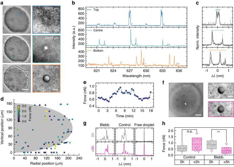
Mechanical forces are key regulators of cellular behavior and function, affecting many fundamental biological processes such as cell migration, embryogenesis, immunological responses, and pathological states. Specialized force sensors and imaging techniques have been developed to quantify these otherwise invisible forces in single cells and in vivo. However, current techniques rely heavily on high-resolution microscopy and do not allow interrogation of optically dense tissue, reducing their application to 2D cell cultures and highly transparent biological tissue. Here, we introduce DEFORM, deformable microlaser force sensing, a spectroscopic technique that detects sub-nanonewton forces with unprecedented spatio-temporal resolution. DEFORM is based on the spectral analysis of laser emission from dye-doped oil microdroplets and uses the force-induced lifting of laser mode degeneracy in these droplets to detect nanometer deformations. Following validation by atomic force microscopy and development of a model that links changes in laser spectrum to applied force, DEFORM is used to measure forces in 3D and at depths of hundreds of microns within tumor spheroids and late-stage Drosophila larva. We furthermore show continuous force sensing with single-cell spatial and millisecond temporal resolution, thus paving the way for non-invasive studies of biomechanical forces in advanced stages of embryogenesis, tissue remodeling, and tumor invasion.


Conflict of interest statement

The authors declare no competing interests.

Figures

Fig. 1
Fig. 1. Principle of deformable microlaser force sensing.
a Sketch of whispering gallery modes inside microscopic spherical droplets for three different azimuthal mode numbers m = 115, 113, and 85. Shown are the surface projections of the electromagnetic field (left half of the spheres) and the cross section of the modes inside the droplets (right half of the spheres). Scale bar, 2 µm. b Calculated mode splitting upon deformation of a 15 µm diameter spherical droplet into an ellipsoid with oblate geometry. Lifting of the mode degeneracy causes the single mode to split into broad bands. A zoomed-in view of the transverse electric mode TE115 shows that the approximately 1 nm wide band consists of 115 azimuthal modes. The inset shows an oblate ellipsoid with the equatorial semi-axis a, polar semi-axis b, and b < a. c Size distribution of droplets fabricated in a high throughput microfluidic chip. Inset: Fluorescence microscopy image of the fabricated droplets. Scale bar, 15 µm. d Droplet diameters and size distributions for batches of droplets that were fabricated under different flow conditions. Data are offset vertically for clarity. Error bars indicate standard error of the mean
Fig. 2
Fig. 2. DEFORM reliably measures sub-nanonewton forces.
a Schematic illustration of the deformation of single microlaser droplets by an atomic force microscope (top) and visualization of a typical push-and-release experiment (bottom). b Microlaser spectra detected before, during, and after the application of a 200 pN force with the AFM (symbols as in a). c Typical force-distance curve used to calculate the stiffness of the droplets. d Variation in stiffness for a batch of droplet microlasers (N = 27). Boxplot showing the median and standard deviation, while whiskers represent the 5th and 95th percentile. e Evolution of the microlaser spectrum under increasing applied force. The gray bars below each spectrum indicate the fitted mode splitting, i.e. separation in wavelength between the leading and trailing edge of the mode. All spectra are plotted on the same scale but vertically offset for clarity. f Mode splitting versus force applied by AFM. A linear regression analysis is used to obtain the correlation between laser mode splitting and external force (solid blue line). The gray area marks the error of the measurement used for further calculations of the force. g Lasing spectra of undeformed microlasers doped with 4 different fluorescent dyes, C545T, BODIPY, Nile Red, Rhodamine B (left to right)
Fig. 3
Fig. 3. 3D force sensing in tumor spheroids.
a Left: Differential interference contrast (DIC) microscopy of a 3D tumor spheroid, imaged at 3 different focus planes, at bottom (orange), middle (mint), and top (blue). Scale bar, 100 µm. Right: Contrast enhanced magnifications of regions with a microlaser droplet for each plane. Scale bar: 10 µm. b Lasing spectrum of the droplets in the magnified regions in a). c Overlays of 3 split modes marked with asterisks in each panel in b. The colored bars indicate the fitted peak splitting. Modes in each panel have the same polarization. d Overview of measured forces for N = 5 spheroids. The gray area indicates the average size of the spheroids (with semi-axes a = 90 µm, b = 210 µm), showing the approximate position of the droplets inside the spheroids. e Time-lapse force measurement inside a tumor spheroid. f (left) DIC microscopy image of a multicellular spheroid treated with blebbistatin. Scale bar, 100 µm. (right) Magnified images of the droplet microlaser marked by an arrow in the main panel before (gray) and after (violet) blebbistatin treatment. Scale bar, 10 µm. g Representative emission spectra of droplet microlasers inside spheroids treated with blebbistatin (left) and an untreated control (center) at the start and after 5 h. Also shown are spectra of free droplets outside the spheroid. h Statistical analyses of the effect of blebbistatin. Boxplot showing the mean and standard deviation while a two-sample t-test was used for statistical analysis
Fig. 4
Fig. 4. In vivo force sensing in optically complex Drosophila melanogaster larvae.
a Fluorescence lifetime microscopy image of a 3rd instar Drosophila larva and an injected droplet microlaser. The tissue autofluorescence (gray) and the droplet microlaser (orange) are shown. Scale bar: 200 µm. b 30 min time lapse spectroscopy with 1s temporal resolution of a microlaser inside a Drosophila larva. The contour map shows the spectral intensity plotted on a logarithmic scale. Gaps in the measurement are due to manual readjustments of the microscope stage to keep the droplet microlaser inside the field of view (Supplementary Fig. S7). c DIC microscopy images from the time window highlighted in b (see also Supplementary Video 2). Scale bar: 10 µm. d Kymograph along the pink arrow drawn in c overlaid with the extracted force (pink, right axis). The position of the interface between microlaser and cuticle in the first frame is indicated by a tick mark on the pink arrow. Error bars represent the cumulated maximum uncertainties in the force value. e Maximum intensity projection of top-view multiphoton fluorescence microscopy of a Drosophila larva with GFP labeled musculature. Scale bar: 100 µm. f Cross-sectional view along the dashed white line shown in e. The white dashed line shows the approximate outline of the larva while the white dotted line indicates the position of the substrate. Scale bar: 100 µm. g Bottom-view transmission microscopy images focussed on the bottom (left) and top (middle) of a Drosophila larva. Fluorescence microscopy for the same top plane, revealing a highly blurred image of the injected microlaser droplet (right). Scale bar: 100 µm. h in vivo high-speed force transient with sub-nanonewton resolution measured at 10 Hz inside the larva shown in g

Similar articles

Cited by

References

    1. Wu PH, et al. A comparison of methods to assess cell mechanical properties. Nat. Methods. 2018;15:491–498. doi: 10.1038/s41592-018-0015-1. - DOI - PMC - PubMed
    1. Gómez-González M, et al. Measuring mechanical stress in living tissues. Nat. Rev. Phys. 2020;2:300–317. doi: 10.1038/s42254-020-0184-6. - DOI
    1. Roca-Cusachs P, Conte V, Trepat X. Quantifying forces in cell biology. Nat. Cell Biol. 2017;19:742–751. doi: 10.1038/ncb3564. - DOI - PubMed
    1. Doubrovinski K, et al. Measurement of cortical elasticity in Drosophila melanogaster embryos using ferrofluids. Proc. Natl Acad. Sci. USA. 2017;114:1051–1056. doi: 10.1073/pnas.1616659114. - DOI - PMC - PubMed
    1. Serwane F, et al. In vivo quantification of spatially varying mechanical properties in developing tissues. Nat. Methods. 2017;14:181–186. doi: 10.1038/nmeth.4101. - DOI - PMC - PubMed

LinkOut - more resources