. 2024 Jun 4;14(1):12834.
doi: 10.1038/s41598-024-63610-x.

Compact metamaterial-based single/double-negative/near-zero index resonator for 5G sub-6 GHz wireless applications

Affiliations

Compact metamaterial-based single/double-negative/near-zero index resonator for 5G sub-6 GHz wireless applications

Sura Khalil Ibrahim et al. Sci Rep. .

Abstract

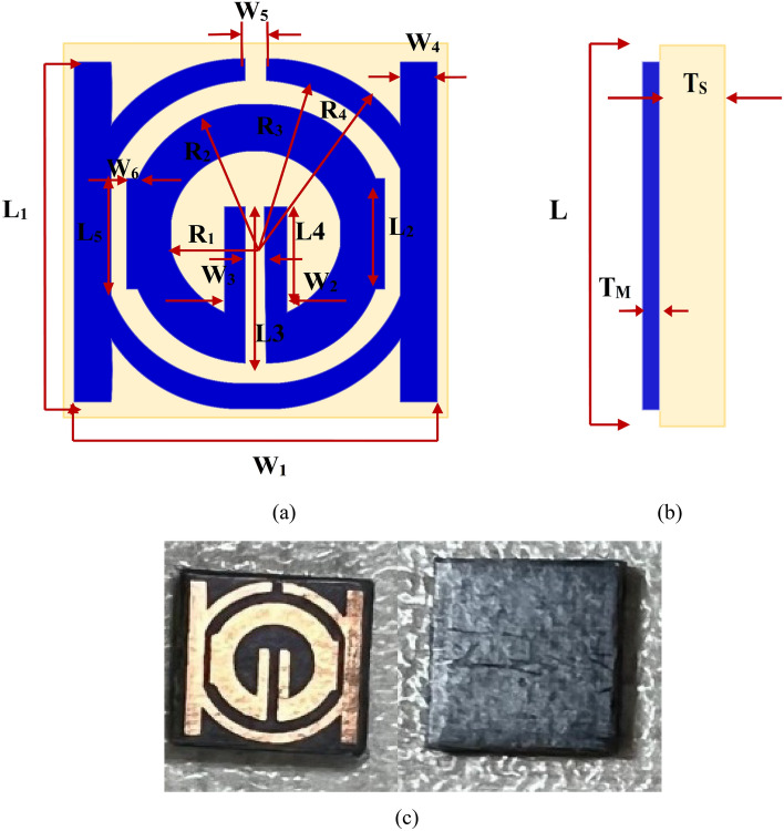
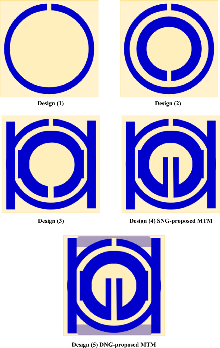
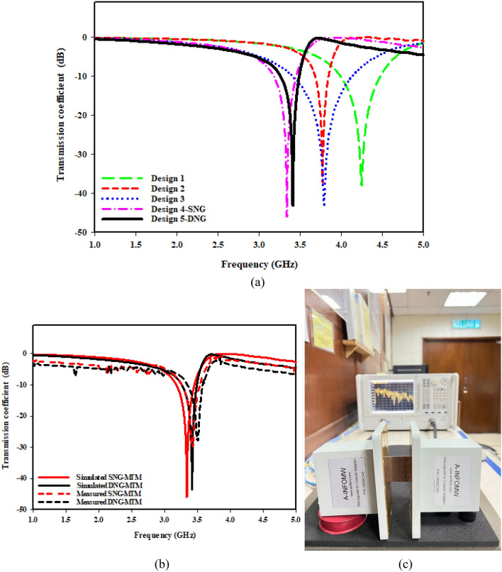
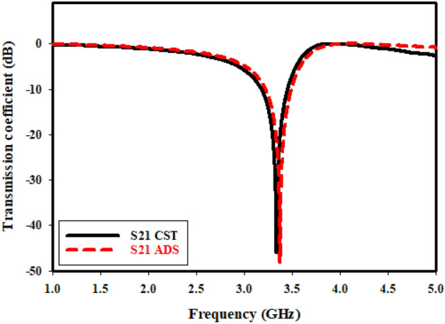
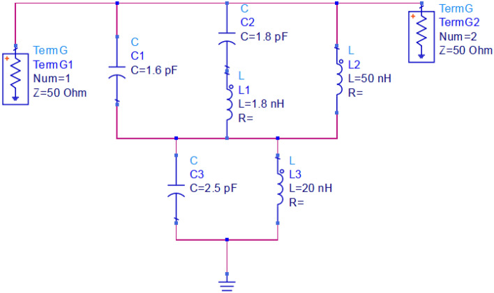
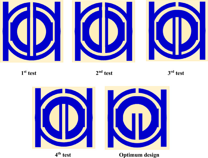
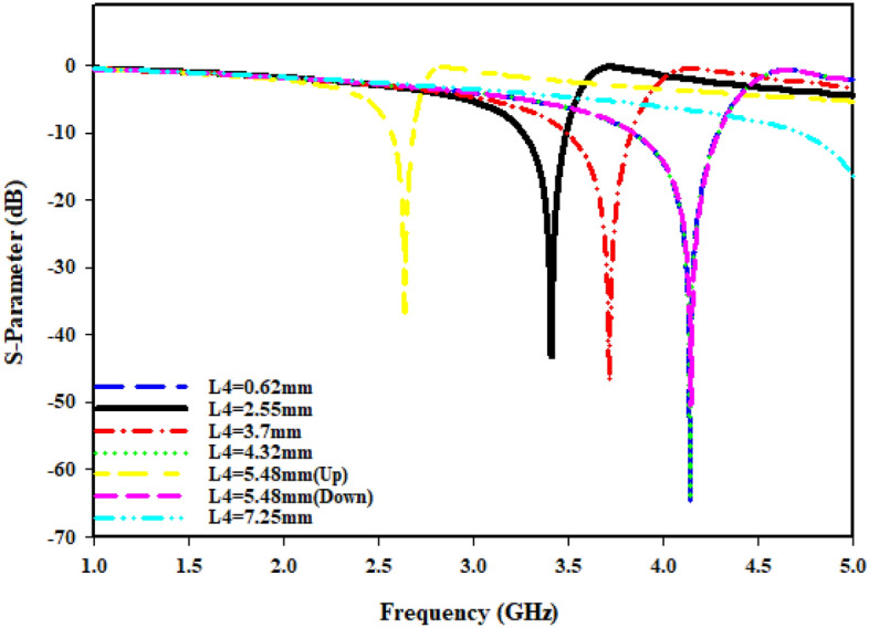
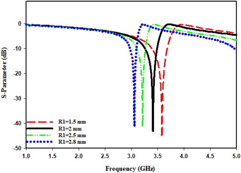
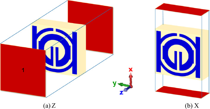
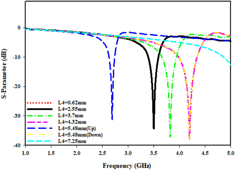
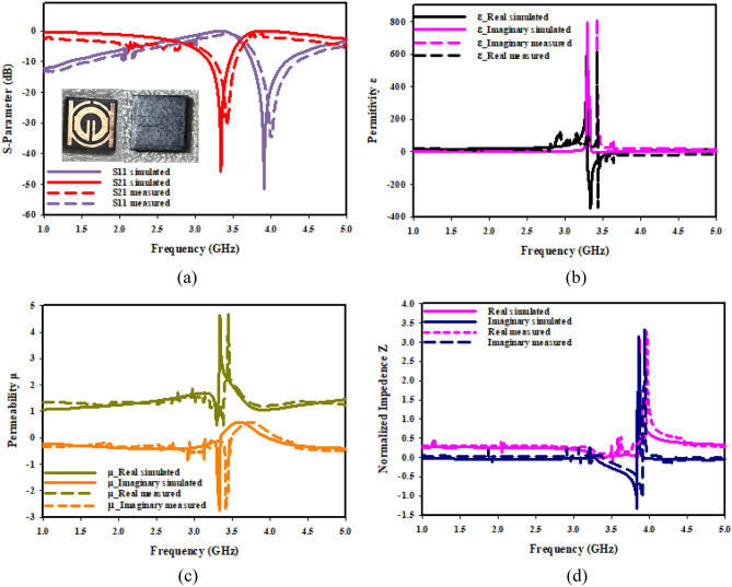
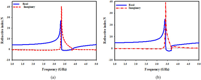
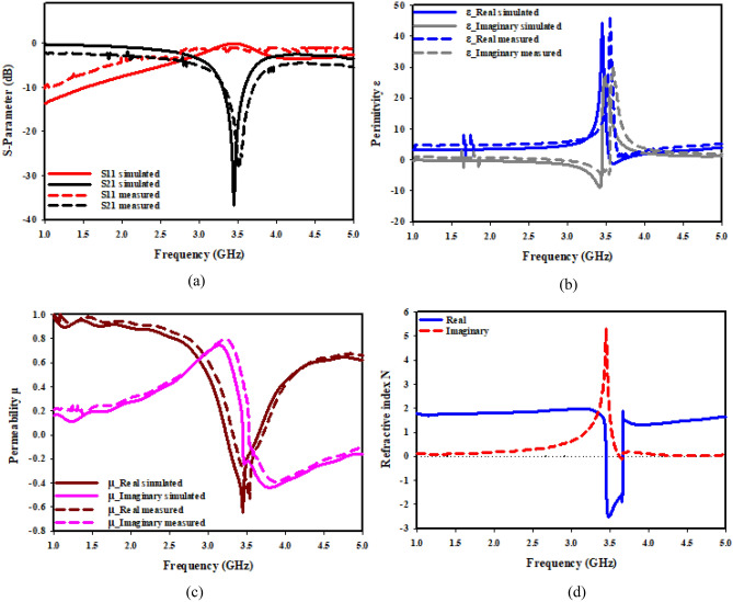
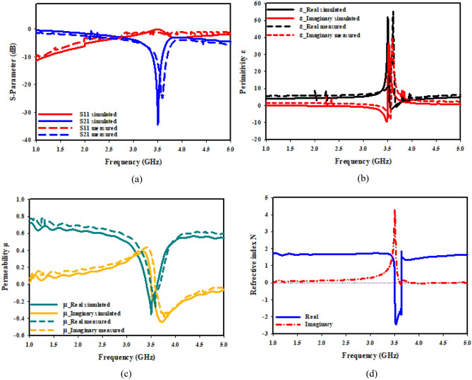
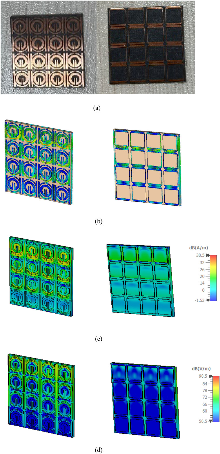
The concept, performance, and analyses of distinctive, miniaturized metamaterial (MTM) unit cell addressing the forthcoming Sub 6 GHz 5G applications are presented in this paper. Two circular split-ring resonators (CSRR) with two parallel rectangular copper elements in front of the design and a slotted square element in the background make up the suggested metamaterial. It has a line segment with tunable features that is positioned in the center of the little ring copper structure. The suggested design offers a significant operating frequency band of 220 MHz together with a resonance of transmission coefficient S21 at 3.5 GHz. Furthermore, in two (z & x) principal axes of wave propagation, wide-range achievement, single/double-negative (S/DNG) refractive index, negative permittivity, and near-zero permeability properties were demonstrated. Through varying central slotted-strip line length, resonance frequencies can be selectively altered. Moreover, the metamaterial has overall dimensions of 9 × 9 mm2 and is composed on a Rogers 5880 RT substrate. In order to create the suggested MTM's equivalent circuit, which shows similar coefficient of transmission (S21), a proposed design's numerical simulation is carried out in the CST micro-wave studio. This simulation is after that put to comparison with manufacturing of the design.

Keywords: 5G sub-6 GHz; DNG (double negative) metamaterial; ENG (electrical or epsilon negative); MNG (magnetic negative); Near-zero Index; SNG (single negative); Wireless communication.


Conflict of interest statement

The authors declare no competing interests.

Figures

Figure 1
Figure 1
Proposed SNG-MTM unit cell: (a) simulated front view; (b) simulated side view; (c) Top and bottom of fabricated MTM.
Figure 2
Figure 2
Proposed DNG-MTM unit cell: (a) simulated total, front and back view; (b) back side view; and (c) side view (simulated); (d) Top and bottom of fabricated MTM.
Figure 3
Figure 3
Evaluation steps toward the metamaterial design.
Figure 4
Figure 4
(a) Transmission coefficient for evolution steps toward the proposed MTM; (b) Simulated and fabricated of transmission coefficient with; (c) Setup for testing of proposed MTM.
Figure 5
Figure 5
S21 comparison of the equivalent circuit result with simulation.
Figure 6
Figure 6
Equivalent circuit model.
Figure 7
Figure 7
Tuning slotted-strip line of the proposed MTM.
Figure 8
Figure 8
Transmission coefficient for evolution steps toward the proposed MTM with L4.
Figure 9
Figure 9
Transmission coefficient for evolution steps toward the proposed MTM with R1.
Figure 10
Figure 10
Metamaterial simulation set up: (a) on Z-axis; (b) on X-axis.
Figure 11
Figure 11
Transmission coefficients tuning when repositioning the ports in the X-direction for L4.
Figure 12
Figure 12
Transmission coefficients tuning when repositioning the ports in the X-direction for R1.
Figure 13
Figure 13
Analysis current distribution for proposed-MTM; (a) SNG-MTM; (b) front view; (c) back view for DNG-MTM; and (d) front and back view for copper of DNG-MTM for resonant frequency 3.5 GHz.
Figure 14
Figure 14
Analysis the magnetic field distribution for proposed-MTM; (a) SNG -MTM; (b) front view; (c) back view for DNG-MTM; and (d) front and back view for copper of DNG-MTM for resonant frequency 3.5 GHz.
Figure 15
Figure 15
Analysis the electric field distribution for proposed-MTM; (a) without slotted square BG; (b) front view; (c) back view; and (d) front and back view for DNG-MTM with slotted-square BG for resonant frequency 3.5 GHz.
Figure 16
Figure 16
SNG–MTM parameters (a) S-parameter; (b) permittivity; (c) permeability; (d) normalized impedance.
Figure 17
Figure 17
DNG-MTM parameters (a) S-parameter; (b) permittivity; (c) permeability; (d) normalized impedance.
Figure 18
Figure 18
Refractive index of the proposed MTM: (a) SNG-MTM; (b) DNG-MTM.
Figure 19
Figure 19
X-axis effective parameter of SNG –MTM: (a) S-parameter; (b) permittivity; (c) permeability; (d) refractive index.
Figure 20
Figure 20
X-axis effective parameter of DNG–MTM: (a) S-parameter; (b) permittivity; (c) permeability; (d) refractive index.
Figure 21
Figure 21
Analysis for (4 × 4) SNG-MTM array: (a) fabricated design ofv16 array elements; (b) current distribution; (c) magnetic field distribution; (d) electric field distribution for resonant frequency 3.5 GHz.
Figure 22
Figure 22
Effective parameters of the (4 × 4) SNG-MTM array structure: (a) scattering parameters; (b) permittivity; (c) permeability; (d) refractive index.
Figure 23
Figure 23
Analysis for (4 × 4) DNG-MTM array: (a) fabricated design of 16 array elements (b) current distribution; (c) magnetic field distribution; (d) electric field distribution for resonant frequency 3.5 GHz.
Figure 24
Figure 24
Effective parameters of the (4 × 4) DNG-MTM array structure: (a) scattering parameters; (b) permittivity; (c) permeability; (d) refractive index.

References

    1. Hasan MM, Islam MT, Moniruzzaman M, Uddin MH, Sahar NBM, Samsuzzaman M. Bilateral coupled epsilon negative metamaterial for dual band wireless communications. Comput. Mater. Contin. 2022;71(1):1263–1281. doi: 10.32604/cmc.2022.021388. - DOI
    1. Hasan MM, et al. Symmetric engineered high polarization-insensitive double negative metamaterial reflector for gain and directivity enhancement of sub-6 GHz 5G antenna. Materials (Basel) 2022;15(16):2022. doi: 10.3390/ma15165676. - DOI - PMC - PubMed
    1. Saleh CM, Almajali E, Jarndal A, Yousaf J, Aljaafreh SS, Amaya RE. Wideband 5G antenna gain enhancement using a compact single-layer millimeter wave metamaterial lens. IEEE Access. 2023;11:14928–14942. doi: 10.1109/ACCESS.2023.3244401. - DOI
    1. Ibrahim SK, et al. Design, challenges and developments for 5G massive MIMO antenna systems at sub 6-GHz band: A review. Nanomaterials. 2023;13(3):1. doi: 10.3390/nano13030520. - DOI - PMC - PubMed
    1. Al-Bawri SS, Islam MT, Islam MS, Singh MJ, Alsaif H. Massive metamaterial system-loaded MIMO antenna array for 5G base stations. Sci. Rep. 2022;12(1):1–16. doi: 10.1038/s41598-022-18329-y. - DOI - PMC - PubMed