. 2024 Jul 11;187(14):3638-3651.e18.
doi: 10.1016/j.cell.2024.05.002. Epub 2024 Jun 4.

POT1 recruits and regulates CST-Polα/primase at human telomeres

Affiliations

POT1 recruits and regulates CST-Polα/primase at human telomeres

Sarah W Cai et al. Cell. .

Abstract

Telomere maintenance requires the extension of the G-rich telomeric repeat strand by telomerase and the fill-in synthesis of the C-rich strand by Polα/primase. At telomeres, Polα/primase is bound to Ctc1/Stn1/Ten1 (CST), a single-stranded DNA-binding complex. Like mutations in telomerase, mutations affecting CST-Polα/primase result in pathological telomere shortening and cause a telomere biology disorder, Coats plus (CP). We determined cryogenic electron microscopy structures of human CST bound to the shelterin heterodimer POT1/TPP1 that reveal how CST is recruited to telomeres by POT1. Our findings suggest that POT1 hinge phosphorylation is required for CST recruitment, and the complex is formed through conserved interactions involving several residues mutated in CP. Our structural and biochemical data suggest that phosphorylated POT1 holds CST-Polα/primase in an inactive, autoinhibited state until telomerase has extended the telomere ends. We propose that dephosphorylation of POT1 releases CST-Polα/primase into an active state that completes telomere replication through fill-in synthesis.

Keywords: CST; DNA replication; DNA-protein complex; POT1; cryo-EM; end-replication problem; phospho-regulation; polymerase α/primase; shelterin; telomere.


Conflict of interest statement

Declaration of interests T.R.C. is a member of the SAB of Storm Therapeutics, Eikon Therapeutics, and SomaLogic, Inc.

Figures
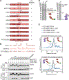
Figure 1.
Figure 1.. Identification of residues promoting the POT1–CST interaction.
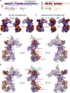
See also Figure S1 and Figure S2. (A) Domain schematics and design of constructs containing chimeric swaps between human POT1 (red) and mouse mPOT1b (salmon). HMb: Human/Mouse POT1b swap; OB: oligosaccharide/oligonucleotide-binding domain; HJRL: Holliday junction resolvase-like domain. The interaction with human CST is indicated as shown in (C). (B) Sequence alignment of the region within the POT1 hinge in POT1, mPOT1b, and POT1(ESDL) showing the location of the ESDL insertion. (C) Co-IPs of Myc-tagged POT1/mPOT1b chimeras and FLAG-tagged Ctc1 from 293T cells transfected with Myc-POT1 (and variants), FLAG-TPP1, FLAG-Ctc1, FLAG-Stn1, and FLAG-Ten1. Western blots of Myc IPs were probed with anti-Myc and anti-FLAG antibodies to detect POT1 and Ctc1, respectively. POT1 construct details and names are provided in (A). (D) Coomassie-stained SDS-PAGE gels and cartoon schematics of the purified POT1/TPP1 and CST proteins used for fluorescent-detection size-exclusion chromatography (FSEC) analysis. (E) FSEC analysis of the interaction between CST and POT1(WT)/GFP-TPP1 (black) or POT1(ESDL)/GFP-TPP1 (blue) in the absence (top) or presence (bottom) of telomeric ssDNA. Traces without CST are shown as dashed lines and color key is the same for both panels. RFU: relative fluorescence units.
Figure 2.
Figure 2.. Cryo-EM structures of CST–POT1(ESDL)/TPP1 complexes.
See also Figure S3 and Figure S4. (A) Domain organization of CST and the shelterin subunits POT1(ESDL) and TPP1. Regions of TPP1 not observed in the cryo-EM maps are shown at 50% opacity. Dashed lines indicate regions not included in the expression construct. *The TPP1 serine-rich linker was included in the apo complex but not the ssDNA-bound complex. See also Fig. S2C. ARODL: Acidic Rpa1 OB-binding Domain-Like 3-helix bundle; wH: winged helix-turn-helix domain; RD: recruitment domain, TID: TIN2-interacting domain. For other abbreviations see Fig. 1. (B) Cryo-EM density map (contour threshold 0.15) of apo CST–POT1(ESDL)/TPP1 at 3.9-Å resolution (see also Fig. S3). (C) Cryo-EM density map (contour threshold 0.15) of ssDNA-bound CST–POT1(ESDL)/TPP1 at 4.3-Å resolution (see also Fig. S4). (D-E) Atomic models for the apo (D) and ssDNA-bound (E) CST–POT1(ESDL)/TPP1 complexes, respectively. See also Video S1.
Figure 3.
Figure 3.. Phosphorylation-dependent interaction of POT1(ESDL) with CST.
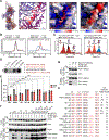
See also Figure S5. (A) Interaction between the POT1 CCIR and Ctc1. (Left) The black box indicates the region of the apo CST–POT1(ESDL)/TPP1 model shown in the right panels. (Right) Zoomed-in view showing surface electrostatic potential analysis of the POT1(ESDL) CCIR interacting with Ctc1OB-D. The POT1(ESDL) CCIR is shown in cartoon (left) and surface (right) representation with electrostatic potential colored from red (−10 kBT/e) to white (0 kBT/e) to blue (+10 kBT/e) (see also Fig. S5B). The ESDL insertion is colored salmon as in Fig. 1A, and residue numbering corresponds to the WT human POT1 sequence. (B) FSEC analysis of the phosphorylation-dependent interaction between CST and POT1(WT)/GFP-TPP1 (left, black) and POT1(ESDL)/GFP-TPP1 (right, blue) in the presence of telomeric ssDNA (see also Fig. S5C–D). Traces without CST are shown as dashed lines, and traces containing POT1/TPP1 that have been treated with λ protein phosphatase (λPP) are shown in red. RFU: relative fluorescence units. The chromatograms for the WT mock and ESDL mock samples are the same as in Fig. 1E. They are reproduced here as the controls for the phosphatase experiment, which was performed simultaneously. (C) Representative MP histograms showing the phosphorylation-dependent interaction between CST and POT1(WT)/GFP-TPP1 (left, black) and POT1(ESDL)/GFP-TPP1 (right, blue) in the presence of telomeric ssDNA (see also Fig. S5E). Experiments with λPP-treated POT1/TPP1 experiments are shown in translucent red. Peak maxima are indicated along with cartoons (peak 1: free POT1/TPP1, peak 2: free CST, peak 3: CST–POT1/TPP1) that correspond to complexes of that molecular mass to within 10%. (D) Kinase assay with HeLa nuclear extract and filter-bound peptides corresponding to the CCIR regions of POT1, mPOT1b, mPOT1a, and POT1(ESDL). Phosphorylation is monitored using incorporation of γ-32P-ATP. (E) Quantification of MP results (Fig. S5E). Proportion bound POT1/TPP1 corresponds to the ratio of total counts in peak 3 (CST–POT1/TPP1 complex) divided by total counts of POT1/TPP1 (peak 1 and peak 3). Error bars represent the S.D. from three technical replicate experiments. POT1 construct details and names are provided in (H). (F - G) Co-IPs of Myc-tagged POT1 protein variants and FLAG-tagged Ctc1 from 293T cells co-transfected with Myc-POT1, FLAG-TPP1, FLAG-Ctc1, FLAG-Stn1, and FLAG-Ten1. Western blots of Myc IPs were probed with anti-Myc and anti-FLAG antibodies to detect POT1 and Ctc1, respectively. Short and long exposures of the anti-FLAG probing for Ctc1 are shown. POT1 construct details and names are provided in (H). (H) Sequences of phosphomimetic, alanine, and CP CCIR mutants. The interaction with CST is indicated as shown in (E-G). The “+” signifies and interaction matching that of the positive control, POT1(ESDL), and “−” signifies no interaction. “++” represents greater interaction than the positive control and “+/−“ and “−/+” indicate slightly weaker interactions in decreasing strength, respectively.
Figure 4.
Figure 4.. CP mutations map to the primary Ctc1–POT1 interface.
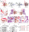
See also Figure S6. (A) Comparison of CST-bound POT1OB-3/TPP1 (this study, colored) to unbound POT1OB-3/TPP1 (PDB 5H65/5UN7, , grayscale). (B) Close-up views of sites of interest at or near the interface between POT1 and Ctc1 (see also Fig. S6A). Residues colored in bright red are mutated in CP. (i) Self-interaction between POT1 Ser322 and Arg367. Hydrogen bonds are shown as yellow dashed lines. CP mutation S322L is predicted to disrupt this linchpin interaction. (ii) Self-interaction between POT1 hinge and C-terminus. (iii) Position of Gly503 in the hydrophobic core of Ctc1ARODL predicts a destabilizing effect of the G503R CP mutation. (iv) Primary hydrophobic interface between POT1 hinge, POT1OB-3, and Ctc1ARODL. CP mutation H484P is predicted to disrupt the hydrophobic stacking interactions with POT1 Pro603 and Ctc1 His488 and Pro483. (v) Salt bridge between POT1 hinge residue Glu325 and Ctc1OB-D residue Arg624. (C) Co-IPs of Myc-tagged POT1 protein variants and FLAG-tagged Ctc1 from 293T cells transfected with Myc-POT1, FLAG-TPP1, FLAG-Ctc1, FLAG-Stn1, and FLAG-Ten1. Western blots of Myc IPs were probed with anti-Myc and anti-FLAG antibodies to detect POT1 and Ctc1, respectively. Short and long exposures of the anti-FLAG probing for Ctc1 are shown. (D) Co-IPs of Myc-tagged POT1(ESDL) and FLAG-tagged Ctc1 WT and CP variants from 293T cells transfected with Myc-POT1, FLAG-TPP1, FLAG-Ctc1, FLAG-Stn1, and FLAG-Ten1. POT1(ESDL) CP contains the S326L mutation, analogous to S322L in POT1CP (see (E)). Western blots of Myc IPs were probed with anti-Myc and anti-FLAG antibodies to detect POT1 and Ctc1, respectively. Short and long exposures of the anti-FLAG probing for Ctc1 are shown. (E) Sequences of CCIR mutants and their interaction with CST as shown in (C-D).
Figure 5.
Figure 5.. POT1OB-2 interacts with the CST ssDNA anchor site, precluding formation of the CST–Polα/primase PIC.
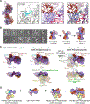
See also Figure S7. (A) Interaction between POT1OB-2 and Ctc1 at the CST ssDNA anchor site. (Left) The black box indicates the region of the apo CST–POT1(ESDL)/TPP1 model shown in the right panels. (Right) Zoomed-in views of the interface. The first panel shows the ssDNA-bound CST structure (PDB 6W6W, gray with DNA colored cyan). The second panel shows the same view of the CST–POT1(ESDL)/TPP1 structure (this study, colored). Ctc1 aa 909–927 (density map shown; contour threshold 0.15) are modeled as poly-alanine stubs, and no ssDNA is bound to Ctc1. The two structures are superposed in panel three. (B) Negative-stain EM 2D averages of ssDNA-bound CST–POT1(ESDL)/TPP1 (left) showing three major conformations depicted by the cartoon schematics (right). 2D averages are flipped or rotated by 90° increments from Fig. S2E into similar orientations for ease of comparison and are sorted by number of particles per class from the most populous class at top left to the least populous class at bottom right. The 2D averages that correspond to each cartoon state are indicated with black, gray, or white circles. The scale bar represents 333 Å (See also Fig. S2E). (C) The CST–POT1(ESDL)/TPP1–ssDNA complex (left) and its superposition with the CST–Polα/primase recruitment complex (RC, PDB 7U5C, middle) and pre-initiation complex (PIC, PDB 8D0B, right). The CST–POT1(ESDL)/TPP1–ssDNA complex is shown as an opaque surface, and CST–Polα/primase complexes are shown in cartoon representation with transparent surfaces. Orthogonal views show that POT1(ESDL)/TPP1 binding does not obstruct the major interface of the RC, but POT1OB-1/2 and Stn1C would interfere with binding of the POLA1 catalytic core to the CST ssDNA anchor site in the PIC (see also Fig. S7A–B). (D) Cartoon schematics showing how CST–POT1/TPP1 is incompatible with PIC formation but could form RC-like complexes in both monomeric and dimeric forms.
Figure 6.
Figure 6.. CST binding enhances POT1/TPP1 inhibition of telomeric C-strand synthesis.
See also Figure S8. (A) DNA synthesis by 50 nM CST–Polα/primase on 50 nM ssDNA templates consisting of 9 or 15 telomeric TTAGGG repeats (9xTEL and 15xTEL, respectively). Products labeled with α-32P-dATP. LC3: an oligonucleotide loading control. (B) Quantification of the data in (A), normalized to reactions without added POT1/TPP1. IC50 +/− uncertainty of the fit to the data points. An independent repeat of the 9xTEL experiment gave equivalent results (Fig. S8A–C). (C) FSEC analysis of the interaction between CST and POT1(ESDL ΔOB1)/GFP-TPP1 in the absence of telomeric ssDNA. The trace without CST is shown as a dashed line. RFU: relative fluorescence units. (D) Design of pre-primed templates to monitor primer extension by Polα. RNA sequence is shown in red. (E) CST–Polα extension of pre-primed templates. M: telomerase reaction products as size markers. The two panels have equal exposure, but one-ninth as much dT42–2xTEL product as 9xTEL product was loaded to compensate for the higher incorporation with the former template. LC1, LC2, LC3: three oligonucleotide loading controls. (F) Quantification of the experiment shown in (E) (left). IC50 values include replicate experiments on separate days, with errors encompassing the range of values obtained. (G) Quantification of the experiment shown in (E) (right). Only partial inhibition occurred at the highest POT1/TPP1 concentrations, so IC50 values were not calculated.
Figure 7.
Figure 7.. Model for telomere maintenance by shelterin and CST–Polα/primase.
(A) Shelterin-mediated telomere protection and maintenance. Shelterin recruits and regulates two telomere maintenance enzymes: telomerase and CST–Polα/primase. Adapted from. (B) Model for the recruitment and regulation of CST–Polα/primase by POT1. CST–Polα/primase is recruited to telomeres in the auto-inhibited RC-like state by phosphorylated POT1, preventing activation of CST–Polα/primase during 5’ end resection and telomerase action following canonical DNA replication. After telomerase has elongated telomeres, a proposed switch results in dephosphorylation of POT1 and subsequent release of CST–Polα/primase to the telomeric ssDNA. When released, CST–Polα/primase can readily form the PIC and execute fill-in synthesis, the final step of telomere replication.

Update of

References

    1. de Lange T (2018). Shelterin-Mediated Telomere Protection. Annu Rev Genet 52, 223–247. - PubMed
    1. Cai SW, and de Lange T (2023). CST-Polα/Primase: the second telomere maintenance machine. Genes Dev 37, 555–569. - PMC - PubMed
    1. Lim CJ, and Cech TR (2021). Shaping human telomeres: from shelterin and CST complexes to telomeric chromatin organization. Nat Rev Mol Cell Biol 22, 283–298. - PMC - PubMed
    1. Takai H, Aria V, Borges P, Yeeles JTP, and de Lange T (2024). CST-polymerase α-primase solves a second telomere end-replication problem. Nature 627, 664–670. - PMC - PubMed
    1. Wu P, Takai H, and de Lange T (2012). Telomeric 3’ overhangs derive from resection by Exo1 and Apollo and fill-in by POT1b-associated CST. Cell 150, 39–52. - PMC - PubMed

LinkOut - more resources