. 2024 Jun 6;15(1):4823.
doi: 10.1038/s41467-024-49052-z.

Superconducting spintronic heat engine

Affiliations

Superconducting spintronic heat engine

Clodoaldo Irineu Levartoski de Araujo et al. Nat Commun. .

Abstract

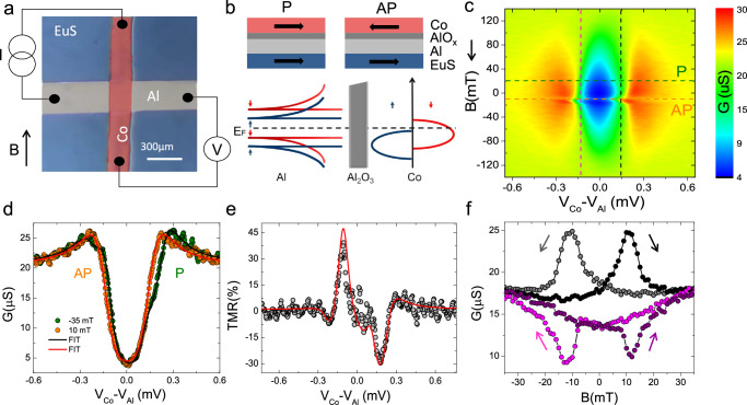
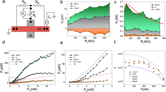
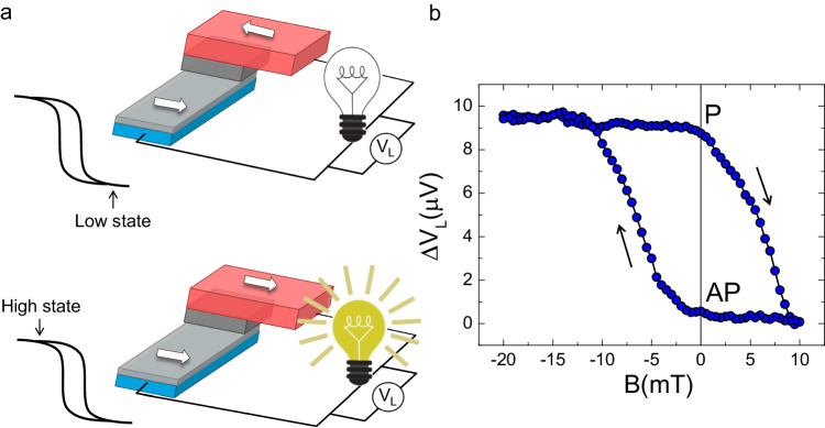
Heat engines are key devices that convert thermal energy into usable energy. Strong thermoelectricity, at the basis of electrical heat engines, is present in superconducting spin tunnel barriers at cryogenic temperatures where conventional semiconducting or metallic technologies cease to work. Here we realize a superconducting spintronic heat engine consisting of a ferromagnetic insulator/superconductor/insulator/ferromagnet tunnel junction (EuS/Al/AlOx/Co). The efficiency of the engine is quantified for bath temperatures ranging from 25 mK up to 800 mK, and at different load resistances. Moreover, we show that the sign of the generated thermoelectric voltage can be inverted according to the parallel or anti-parallel orientation of the two ferromagnetic layers, EuS and Co. This realizes a thermoelectric spin valve controlling the sign and strength of the Seebeck coefficient, thereby implementing a thermoelectric memory cell. We propose a theoretical model that allows describing the experimental data and predicts the engine efficiency for different device parameters.


Conflict of interest statement

The authors declare no competing interests.

Figures

Fig. 1
Fig. 1. Magneto-electric pre-characterization of the superconducting tunnel junction.
a Optical microscope image of one of the samples colored for clarity and a sketch of the 4-wire measurement set-up. The cross bar consist of EuS(13)/Al(16)/AlOx(4)/Co(14), thicknesses are in nm. b Schematic of the sample side view (top) and simplified representation of device density of states (bottom), consisting of the spin-split Al superconducting gap (left) and spin-polarized Co 3d bands (right). c Contour plot of the tunneling conductance (G(V) = dI/dV) measured vs the external magnetic field (B) and the voltage drop across the junction (VCo − VAl). The sweep direction of the magnetic field is indicated by the arrow. d G(V) extracted from c showing parallel (P, green) and antiparallel (AP, orange) configurations. Continuous lines are fit to the experimental data based on the tunneling model as described in the Methods section IVB. e Tunneling magnetoresistance TMR=(RAP - RP)/RP vs voltage drop. The red line is the theoretical expectation for the fits. f G(B) extracted from c for positive and negative voltage drops. The magnetic field sweep directions are indicated by the arrows and a hysteresis is discernible. All measurements were performed at a bath temperature Tbath = 100 mK.
Fig. 2
Fig. 2. Thermoelectric characterization.
a Scheme of the electric circuit used to quantify the thermoelectric response of the device, with the temperature difference obtained via a Joule heating current flowing through the Co strip. b Voltage measured vs heating current, with the positive voltmeter electrode on Co and negative on Al at B = 10 mT. The thermovoltage is obtained by subtracting the Ohmic contribution using the average Vth=V(+IH)+V(IH)2. c Vth measured at ∣IH∣ = 40 μA vs external magnetic field. d Vth measured vs IH for different bath temperatures up to T = 800 mK (top panel) and temperature difference δT = TCo − TAl estimated from model fits to the tunneling spectroscopy, performed at different bath temperatures and heating currents (bottom panel). e Thermovoltage (top) and Seebeck coefficient (S, bottom) vs temperature difference at selected magnetic field values measured at Tbath = 100 mK. Dash-dotted lines represent the fits to the data considering thermoelectricity with (blue) and without (red) rectification effects. f Seebeck coefficient S extracted at different Tbath and IH.
Fig. 3
Fig. 3. Heat engine characterization.
a Scheme of the circuit used for the heat engine measurement. b Voltage developed across the load (VL) measured at different load resistances (RL) for ∣IH∣ = 40 μA at Tbath = 25 mK and three magnetic field values corresponding to different regimes, i.e., P saturation at 10 mT, remanence at 0 mT, and AP configuration at −10 mT. c Power load (PL=VL2RL) extracted from panel (b) vs RL. The red curve is a qualitative fit to the 10 mT data from the maximum transferred power law PL=RLVS2(RL+RS)2, the thermoelectric voltage source VS = Vth ≃ 12.5 μV, and an internal resistance RS ≃ 60 kΩ. d Evolution of PL measured at RL = 150 kΩ and Tbath = 25 mK vs input power (Pin=IH2RCo). e Blow-up of the PL behavior of panel (d). Dash-dotted lines represent the fits to the data considering thermoelectricity with (blue) and without (red) rectification effects. f Efficiency η=PLPin, measured as a function of Tbath at RL = 150 kΩ and IH = 40 μA. Full lines are the theoretical prediction for η for different values of h (see Methods section IVB for details), and evaluated for the junction parameters used in the fit of Fig. 1d.
Fig. 4
Fig. 4. Thermoelectric memory cell.
a Simplified scheme representing the hysteretic behavior of the thermoelectric memory cell. The low state is represented by the AP configuration between the spin-split superconductor and the ferromagnetic cobalt layer, while the high state is in the P configuration characterized by a larger voltage generated across the load resistor. b Evolution of the differential voltage drop across the load (ΔVL=VLPVLAP) measured in the memory cell vs magnetic field B with a load resistor RL = 150 kΩ at Tbath = 300 mK. Note the sizable signal contrast of 10 μV that the memory cell can provide even at zero magnetic fields.

References

    1. DiSalvo FJ. Thermoelectric cooling and power generation. Science. 1999;285:703–706. doi: 10.1126/science.285.5428.703. - DOI - PubMed
    1. Snyder GJ, Toberer ES. Complex thermoelectric materials. Nat. Mater. 2008;7:105–114. doi: 10.1038/nmat2090. - DOI - PubMed
    1. Pelegrini S, et al. Development and characterization of a microthermoelectric generator with plated copper/constantan thermocouples. Microsyst. Technol. 2014;20:585–592. doi: 10.1007/s00542-013-1993-7. - DOI
    1. Sootsman JR, Chung DY, Kanatzidis MG. New and old concepts in thermoelectric materials. Angew. Chem. Int. Ed. 2009;48:8616–8639. doi: 10.1002/anie.200900598. - DOI - PubMed
    1. Roddaro S, et al. Giant thermovoltage in single inas nanowire field-effect transistors. Nano Lett. 2013;13:3638–3642. doi: 10.1021/nl401482p. - DOI - PubMed