Review
. 2024 May 23;10(11):e31703.
doi: 10.1016/j.heliyon.2024.e31703. eCollection 2024 Jun 15.

Surface engineering of pure magnesium in medical implant applications

Affiliations
Review

Surface engineering of pure magnesium in medical implant applications

Mengqi Gong et al. Heliyon. .

Abstract

This review comprehensively surveys the latest advancements in surface modification of pure magnesium (Mg) in recent years, with a focus on various cost-effective procedures, comparative analyses, and assessments of outcomes, addressing the merits and drawbacks of pure Mg and its alloys. Diverse economically feasible methods for surface modification, such as hydrothermal processes and ultrasonic micro-arc oxidation (UMAO), are discussed, emphasizing their exceptional performance in enhancing surface properties. The attention is directed towards the biocompatibility and corrosion resistance of pure Mg, underscoring the remarkable efficacy of techniques such as Ca-deficientca-deficient hydroxyapatite (CDHA)/MgF2 bi-layer coating and UMAO coating in electrochemical processes. These methods open up novel avenues for the application of pure Mg in medical implants. Emphasis is placed on the significance of adhering to the principles of reinforcing the foundation and addressing the source. The advocacy is for a judicious approach to corrosion protection on high-purity Mg surfaces, aiming to optimize the overall mechanical performance. Lastly, a call is made for future in-depth investigations into areas such as composite coatings and the biodegradation mechanisms of pure Mg surfaces, aiming to propel the field towards more sustainable and innovative developments.

Keywords: Biocompatibility; Corrosion resistance; Pure magnesium; Surface modification methods.


Conflict of interest statement

The authors declare that they have no known competing financial interests or personal relationships that could have appeared to influence the work reported in this paper.

Figures

Fig. 1
Fig. 1
The technological development timeline of corrosion studies on pure Mg and surface-modified pure Mg.
Fig. 2
Fig. 2
Mass change of Mg in HBSS at 25 °C: (a) aqueous saturated NaHCO3 and 0.01 kmol/m3 LiOH was used at 25 °C, (b) test specimens were treated with 9 mass% of NaHCO3 and Na2CO3 for 20 h at 25 °C [58].
Fig. 3
Fig. 3
depicts the following: (a) Schematic representation illustrating the binding of oleate groups on Mg(OH)2 and Mg–Al LDH, (b, c) Schematic representation illustrating the interaction of water with the surfaces of LDH and LDH/SO samples [80].
Fig. 4
Fig. 4
Schematic diagrams of alkali-heat treatment on pure Mg surface and its corresponding electrochemical corrosion results: (a) an illustrative depiction showcasing the modification of the pure Mg surface through a layer-by-layer formation of chemical bonds, resulting in the assembly of Mg–OH-AA-BSA. This modification aims to enhance both anti-corrosion properties and osteo-inductive characteristics, (b) electrochemical corrosion results of Mg–OH-AA-BSA [88], (c) a schematic representation detailing the processing mechanism of UMAO-SCA treatment and (d) tafel polarization curves illustrating the electrochemical behavior of Mg plates subjected to various treatments [73].
Fig. 5
Fig. 5
(a) displays the SEM image illustrating the surface of pure Mg samples post-PEO process, highlighting the pore area, (b) 3D topographical maps of pure Mg samples are presented, along with details on surface roughness and contact angle (CA) parameters of the coatings [66].
Fig. 6
Fig. 6
SEM analysis of various advanced coatings formed on pure Mg: (a) SEM micrographs and corresponding linear cross-section EDS analysis profiles showcasing the HAp-coated samples in cross-sectional view [109], (b) proposed formation mechanism of nesquehonite film on the pure Mg substrate and cross-sectional observations of samples [111], and (c) SEM micrographs depicting the surface morphology, along with the corresponding EDS results, of SAMs of SA film [112].
Fig. 7
Fig. 7
(a) FSP - Mg - nHAp sample surface stirred zone, (b) FSP - Mg - nHAp sample cross-section, (c) SEM image of cross-section close to the FSP-Mg-nHAp sample surface in high magnification, (d) cross-section in low magnification, and (e) aggregated nHAp beneath the surface in high magnification [89].
Fig. 8
Fig. 8
Various PVD technologies: schematic of the (a) MS deposition system [147], (b) IBS deposition setup [150], (c) MPPLD system [156], and (d) thermal evaporation deposition system [158].
Fig. 9
Fig. 9
Schematic cross-section of the cathodes used in the (a) HCMS, (b) MS and (c) TMS systems [168].
Fig. 10
Fig. 10
Illustrative instances of biocompatibility research on Mg-based TFMGs include: (a) a schematic representation of the in-vitro cell viability test platform, where L929 cells are cultured on a glass substrate divided into a dot-patterned MgZnCa TFMG array (10 μm × 10 μm × 500 nm) and a bare glass surface, facilitating initial adhesion for cells in a custom-made PDMS chamber (8 mm diameter), (b) assessment of L929 cell viability over 72 h, calculated based on the number of cells attached to the bare slide glass (control) compared to the MgZnCa TFMG, (c) an image depicting implanted PBAT/MgZnCa TFMG and PBAT sample in the back of the ICR mouse, (d) images of H&E stained skin sections at 1 and 3 weeks post-implantation of PBAT/MgZnCa TFMG and PBAT [169], (e) cell staining images captured using a 20X Zeiss fluorescent microscope for pure Mg, Mg36.2Ca7.3Zn56.4, Mg49.6Ca10.5Zn39.9, and Mg60.3Ca21.4Zn18.2, along with an assessment of the indirect cytotoxicity of these samples based on their increasing Zn content [170], (f) biomineralization studies on calcium and ALP assay, (g) cytotoxicity studies on uncoated stainless steel and Mg-based TFMG, and (h) hemocompatibility studies on uncoated stainless steel and Mg-based TFMG [175]. Reproduced based on the cited studies.
Fig. 11
Fig. 11
The cross-section and mechanical properties of the film was deposited from the target of Mg/Si = 50 %: 50 % area ratio: (ac) photographs of cross-sectional and electron diffraction patterns for upper and bottom layers in film, (d) mechanical properties of hardness [183].
Fig. 12
Fig. 12
SEM and TEM micrographs of amorphous metallic glass film surface by PLD: (a) SEM micrograph of MG of Zr59Ti3Al10Cu20Ni8 alloy coated type 304L SS, (b) XRD pattern of amorphous MG of Zr59Ti3Al10Cu20Ni8 alloy coated type 304L SS [201], (c) SEM micrographs of Al–Mg–B–Ti films synthesized by femtosecond PVD, (d) bright field TEM image of Al–Mg–B–Ti films synthesized by femtosecond PVD (plan view) [202].
Fig. 13
Fig. 13
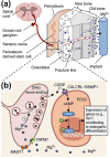
A schematic representation of the mechanism through which Mg2+ promote bone formation: (a) the diffusion of Mg2+ derived from the implant across the bone towards the periosteum, which is innervated by DRG sensory neurons and enriched with PDSCs undergoing osteogenic differentiation into new bone, (b) released Mg2+ enters DRG neurons via Mg2+ transporters or channels (i.e., MAGT1 and TRPM7), promoting the accumulation and exocytosis of CGRP vesicles. The CGRP released by DRG then activates the CGRP receptor in PDSCs (consisting of CALCRL and RAMP1), triggering the phosphorylation of CREB1 via cAMP and promoting the expression of genes contributing to osteogenic differentiation [212].
Fig. 14
Fig. 14
Comparison of Young's modulus between different materials and cortical bone [208,210].
Fig. 15
Fig. 15
Mechanical properties of pure Mg after surface modification: (a) tensile yield strength of the pure Mg and MAO-coated pure Mg over time [67], (b) tensile strength of the pure Mg and HA-coated pure Mg over time [77], (c) bonding strength between different coatings and Mg substrates, asterisks(*) indicate statistical significance, p < 0.05 [106], (d) and biomechanical test of maximum compressive load of the fractured rat femora 4 weeks after implantation with IMN or Mg-IMN in conjunction with treatment of AdV-NC, AdV-Ramp1 or AdV-shRamp1. n = 6 animals per group. *P < 0.05, **P < 0.01, ***P < 0.001, n.s., P > 0.05 by one-way ANOVA with Newman-Keuls post hoc test [212].
Fig. 16
Fig. 16
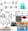
Enhancing bone implant properties through coating processes: (a) key steps in the sol-gel preparation and application of HAp through dip and spin coating techniques [255], (b) process of electro - deposition for HAp coating [256], (c) process of Nd: YAG (532 nm) PLD technique for HAp coating [257], (d) combining fluorination and hydrothermal methods to fabricate CDHA/MgF2 bilayer nano-coating on high-purity Mg surface [106], and (e) process of fabricating PEO/LDH coating [248].

Similar articles

Cited by

References

    1. Rupp F., Geis‐Gerstorfer J., Geckeler K.E. Dental implant materials: surface modification and interface phenomena. Adv. Mater. 2010;8 doi: 10.1002/adma.19960080316. - DOI
    1. Yigit O., Gurgenc T., Dikici B., Kaseem M., Boehlert C., Arslan E. Surface modification of pure Mg for enhanced biocompatibility and controlled biodegradation: a study on graphene oxide (GO)/Strontium apatite (SrAp) biocomposite coatings. Coatings. 2023;13 doi: 10.3390/coatings13050890. - DOI
    1. Pietrzak W.S. Principles of development and use of absorbable internal fixation. Tissue Eng. 2000;6:425–433. doi: 10.1089/107632700418128. - DOI - PubMed
    1. Biehl V., Wack T., Winter S., Seyfert U.T., Breme J. Evaluation of the haemocompatibility of titanium based biomaterials. Biomol. Eng. 2002:19. doi: 10.1016/S1389-0344(02)00016-3. - DOI - PubMed
    1. Kassab E., Marquardt A., Neelakantan L., Frotscher M., Schreiber F., Gries T., Jockenhoevel S., Gomes J., Eggeler G. On the electropolishing of NiTi braided stents - challenges and solutions. Materialwiss. Werkstofftech. 2014;45:920–929. doi: 10.1002/mawe.201400220. - DOI

LinkOut - more resources