

Tailoring focal plane component intensities of polarization singular fields in a tight focusing system
- PMID: 38866872
- PMCID: PMC11169354
- DOI: 10.1038/s41598-024-64392-y
Tailoring focal plane component intensities of polarization singular fields in a tight focusing system
Abstract
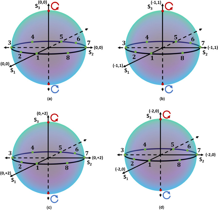
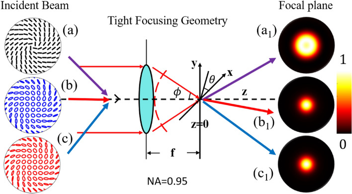
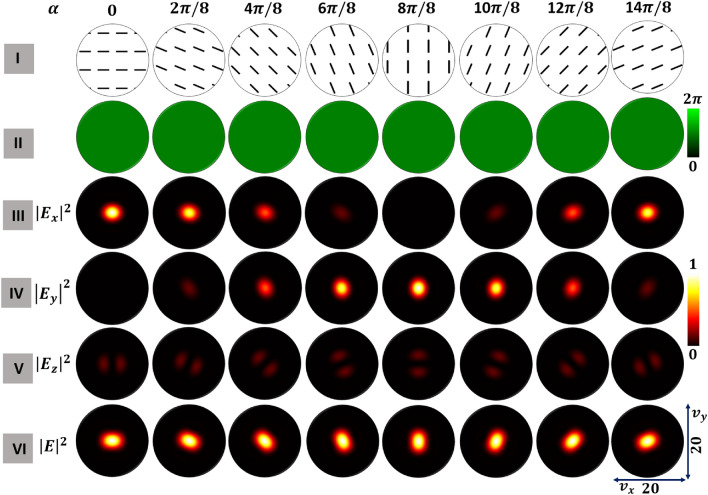
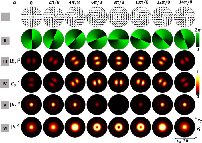
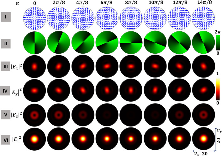
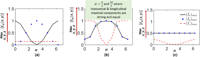
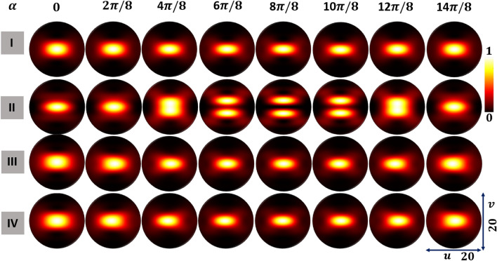
The scientific community studies tight focusing of radially and azimuthally-polarized vector beams as it is a versatile solution for many applications. We offer a new method to produce tight focusing that ensures a more uniform intensity profile in multiple dimensions, providing a more versatile and stable solution. We manipulate the polarization of the radially and azimuthally polarized vector beams to find an optimal operating point. We examine in detail optical fields whose polarization states lie on the equator of the relevant Poincaré spheres namely, the fundamental Poincaré sphere, the hybrid order Poincaré sphere (HyOPS), and the higher order Poincaré sphere. We find via simulation that the fields falling on these equators have focal plane intensity distributions characterized by a single rotation parameter determining the individual state of polarization. The strengths of the component field distributions vary with and can be tuned to achieve equal strengths of longitudinal (z) and transverse (x and y) components at the focal plane. Without control of this parameter (e.g., using in radially and in azimuthally-polarized vector beams) intensity in x and y components are at 20% of the z component. In our solution with , all components are at 80% of the maximum possible intensity of z. In examining the impact of on a tightly focused beam, we also found that a helicity inversion of HyOPS beams causes a rotation of 180 degree in the axial intensity distribution.
© 2024. The Author(s).
Conflict of interest statement
The authors declare no competing interests.
Figures
Similar articles
-
Focusing properties of arbitrary optical fields combining spiral phase and cylindrically symmetric state of polarization.J Opt Soc Am A Opt Image Sci Vis. 2018 Jun 1;35(6):1014-1020. doi: 10.1364/JOSAA.35.001014. J Opt Soc Am A Opt Image Sci Vis. 2018. PMID: 29877346
-
Tight focusing of the vector optical field with polarization varying along complex curves of the Poincaré sphere.Appl Opt. 2024 Apr 1;63(10):2683-2688. doi: 10.1364/AO.519214. Appl Opt. 2024. PMID: 38568552
-
On-demand tailored vector beams.Appl Opt. 2017 Aug 20;56(24):6967-6972. doi: 10.1364/AO.56.006967. Appl Opt. 2017. PMID: 29048043
-
Managing focal fields of vector beams with multiple polarization singularities.Appl Opt. 2016 Nov 10;55(32):9049-9053. doi: 10.1364/AO.55.009049. Appl Opt. 2016. PMID: 27857288
-
Generation and tight focusing of hybridly polarized vector beams.Opt Express. 2010 Dec 20;18(26):27650-7. doi: 10.1364/OE.18.027650. Opt Express. 2010. PMID: 21197039
References
-
- Samlan CT, Suna RR, Naik DN, Viswanathan NK. Spin-orbit beams for optical chirality measurement. Appl. Phys. Lett. 2018;112:031101. doi: 10.1063/1.5008732. - DOI
LinkOut - more resources
Full Text Sources
Research Materials
Miscellaneous
