. 2024 Jul;11(3):034311.
doi: 10.1117/1.NPh.11.3.034311. Epub 2024 Jun 12.

OpenSTED: open-source dynamic intensity minimum system for stimulated emission depletion microscopy

Affiliations

OpenSTED: open-source dynamic intensity minimum system for stimulated emission depletion microscopy

Stephanie A Pierce et al. Neurophotonics. 2024 Jul.

Abstract

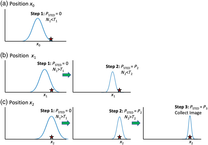
Significance: Stimulated emission depletion (STED) is a powerful super-resolution microscopy technique that can be used for imaging live cells. However, the high STED laser powers can cause significant photobleaching and sample damage in sensitive biological samples. The dynamic intensity minimum (DyMIN) technique turns on the STED laser only in regions of the sample where there is fluorescence signal, thus saving significant sample photobleaching. The reduction in photobleaching allows higher resolution images to be obtained and longer time-lapse imaging of live samples. A stand-alone module to perform DyMIN is not available commercially.

Aim: In this work, we developed an open-source design to implement three-step DyMIN on a STED microscope and demonstrated reduced photobleaching for timelapse imaging of beads, cells, and tissue.

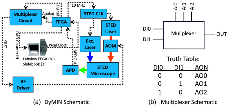
Approach: The DyMIN system uses a fast multiplexer circuit and inexpensive field-programmable gate array controlled by Labview software that operates as a stand-alone module for a STED microscope. All software and circuit diagrams are freely available.

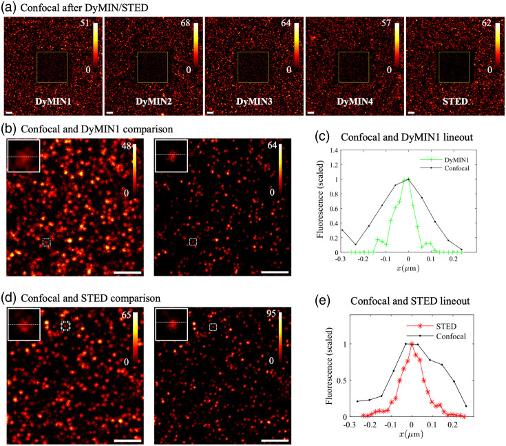
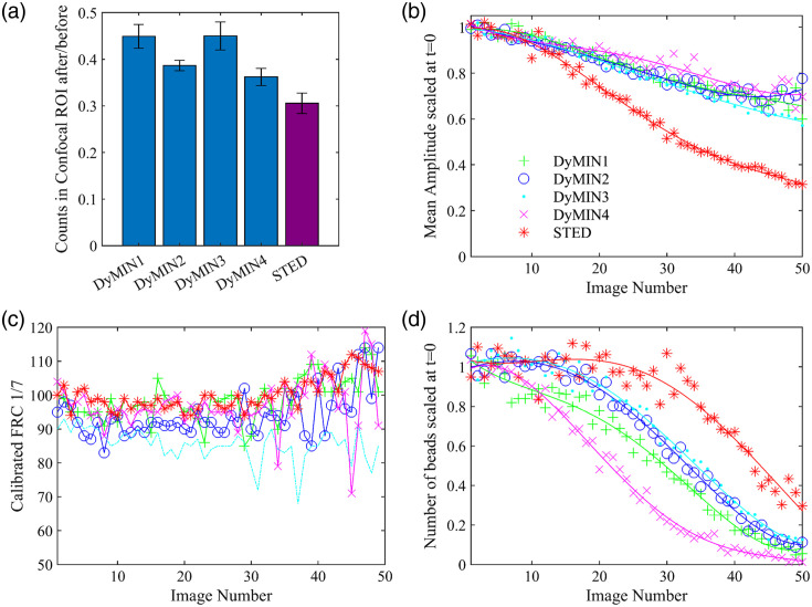
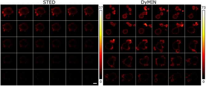
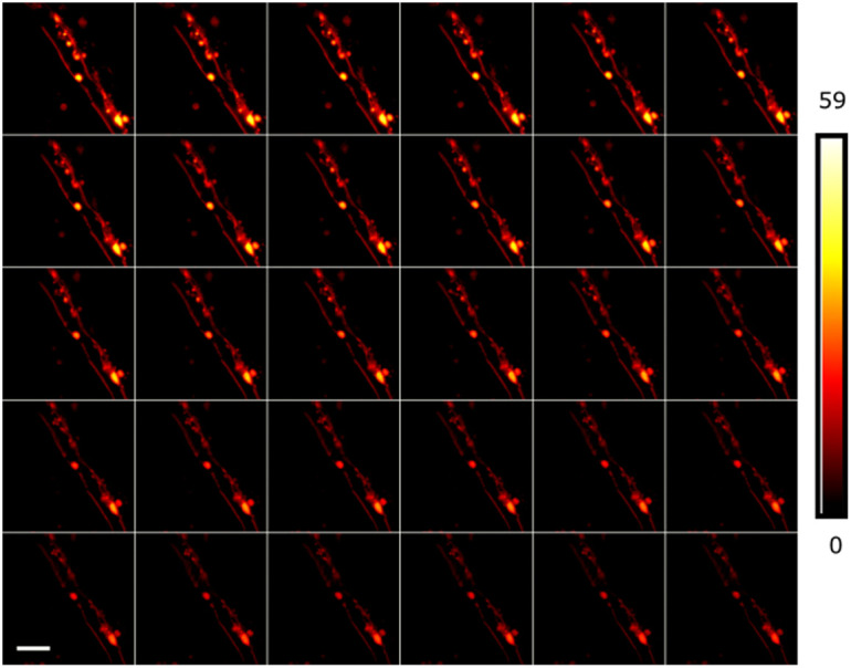
Results: We compared time-lapse images of bead samples using our custom DyMIN system to conventional STED and recorded a 46 % higher signal when using DyMIN after a 50-image sequence. We further demonstrated the DyMIN system for time-lapse STED imaging of live cells and brain tissue slices.

Conclusions: Our open-source DyMIN system is an inexpensive add-on to a conventional STED microscope that can reduce photobleaching. The system can significantly improve signal to noise for dynamic time-lapse STED imaging of live samples.

Keywords: dynamic minimum; fluorescence; microscopy; stimulated emission depletion; super-resolution.


Figures

Fig. 1
Fig. 1
Three-step DyMIN STED algorithm process shown for three different positions as the scan approaches a fluorophore. (a) The initial step collects photons with no STED power applied at x0. Because the fluorophore is outside the collection region, the photons counted (N1) are less than the user supplied threshold for that step (T1) so the process is aborted after step 1 and the scan moves to the next position, x1. (b) The number of counts achieves threshold (N1>T1) for step 1 and step 2 initiates, where the STED power (P2) is applied. However, with the smaller PSF the number of fluorescent photons collected does not meet the threshold (N2<T2), and the process is aborted after step 2. The beam is scanned to position x2, shown in panel (c), where it overlaps with the fluorophore. In this case, the thresholds for step 1 and step 2 (N1>T1 and N2>T2) are met and the final DyMIN step, step 3, is implemented. N3 photons are collected with the maximum STED power (P3) and recorded at that position.
Fig. 2
Fig. 2
Hardware implementation of the DyMIN add on to our STED microscope. (a) An FPGA runs the DyMIN algorithm. A 10 MHz output from the FPGA is used to synchronize a function generator (STED CLK) that triggers the STED and excitation laser. The inputs to the FPGA are the digital photon counting signal from the avalanche photodiode (APD) and a pixel clock from the computer DAQ controlled by software for image acquisition. The FPGA then outputs the modified APD counter signal back to the computer DAQ as the photon signal recorded by the acquisition software. Additionally, three analog outputs and two digital outputs from the FPGA are sent to a multiplexer circuit to control the STED laser power at the different DyMIN steps. (b) A simplified schematic of the multiplexer and truth table. The circuit outputs the analog value (AI0-2) for the different DyMIN steps based on the digital inputs (DI0-1). The output from the multiplexer controls the AOM RF driver, to select the appropriate STED laser power.
Fig. 3
Fig. 3
(a) Schematic of custom-built STED microscope for imaging YFP/GFP with 485 nm excitation laser and 585/600 nm STED laser. Both excitation/STED beams pass through a bandpass filter and a half waveplate and polarizer for power control. An AOM in the STED laser path controls the STED power for the DyMIN algorithm. The lasers are each coupled into a PM fiber, collimated, and the STED laser is sent through a vortex phase mask before being combined with the excitation laser using a dichroic. A quarter waveplate sets the polarization to be circular, followed by the Yanus 2D galvo scanning system, scan lens, tube lens, and objective lens, which focuses the beams onto the sample. The resulting fluorescence is selected using a dichroic and bandpass filter, coupled into a multimode fiber that acts as a confocal pinhole, then sent to the APD. (b) The STED resolution calibration curve. The resolution of the STED microscope at a series of STED laser power values was estimated by imaging 23 nm fluorescent beads. These values were fit to a curve (orange line) using Eq. (1). Example values from our bead imaging experiments of P1, P2, and P3 are indicated with green vertical lines.
Fig. 4
Fig. 4
(a) Confocal images of a 30×30  μm FOV centered on the same location where DyMIN1-DyMIN4 and conventional STED 50-image sequences (see Table 1 for imaging parameters) were taken of a 45 nm fluorescent bead sample with 10×10  μm field and 512×512  pixels, after the DyMIN/STED sequences were acquired, as labeled. (b) Confocal image versus DyMIN1 image with a select bead lineout shown in panel (c) indicating a smaller FWHM of the bead with DyMIN super resolution imaging. Similar results are found for DyMIN2-4 (not shown). (d) Confocal image versus conventional STED image with a selected bead lineout shown in panel (e) with similar reduction in the FWHM. Colorbars are scaled to the maximum value of the image. Scalebars are 2  μm.
Fig. 5
Fig. 5
Analysis of photobleaching and resolution for DyMIN and STED images of fluorescent beads. (a) The ratio of the total confocal fluorescence counts in the DyMIN/STED imaging ROI [shown in Fig. 4(a)] after the 50-image sequence compared to before. Error bars were calculated by splitting the ROI into nine equal regions and calculating the standard deviation. (b) The mean amplitude of 2D Lorentzian fits of the beads verses image number, scaled to the mean of the initial three values. Fits were performed on a 15×15  pixel ROI around the bead center, selected using a peak finding routine in MATLAB. The lines are fourth degree polynomial fits to guide the eye. (c) The FRC, calculated with a fixed 1/7 threshold, verses image number, with the FRC calculated between subsequent images of the sequence (i,i+1), with individual curves for each image sequence. The close initial values indicate that the STED powers were equivalent during imaging. (d) The number of beads fit in panel (b) verses image number, scaled to the mean of the initial three values, also with a fourth degree polynomial fit. All traces in panels (b)–(d) use the color and marker scheme shown in the legend in panel (b).
Fig. 6
Fig. 6
A sequence of 30 images (left to right, top to bottom), taken 30 s apart, with a 23×23  μm FOV with 600×600  pixels of wild type T cells expressing lifeactGFP. A 5  μm scalebar is shown in the bottom right STED image. The STED sequence on the left quickly bleaches so that by the middle of the sequence the image is no longer visible on the same scale as the first image, whereas the DyMIN sequence is still visible even on the 30’th image. The DyMIN settings were P=(0,1.4,12.7)  mW, T=(3,4) counts and t=(3.6,6.2,10)  μs. A dwell time of 10  μs was used for the conventional STED sequence at P=24  mW.
Fig. 7
Fig. 7
Time series images of a live cerebellar brain slice from a PLP-eGFP mouse using DyMIN imaging (left to right, top to bottom). A 20×23  μm FOV with 512×512  pixels was imaged using DyMIN parameters T=(12,12) counts, t=(3.6,5,4)  μs and with powers of P=(0,5,18.3)  mW. A 30 image timeseries was taken at 30 s between the start of each image. The sample remains visible throughout the entire imaging sequence. A 5  μm scalebar is shown in the bottom left image.

Similar articles

Cited by

References

    1. Stefan W. H., Jan W., “Breaking the diffraction resolution limit by stimulated emission: stimulated-emission-depletion fluorescence microscopy,” Opt. Lett. 19, 780 (1994).OPLEDP10.1364/OL.19.000780 - DOI - PubMed
    1. Thomas A. K., et al. , “Fluorescence microscopy with diffraction resolution barrier broken by stimulated emission,” Proc. Natl. Acad. Sci. U. S. A. 97, 8206–8210 (2000).10.1073/pnas.97.15.8206 - DOI - PMC - PubMed
    1. Balzarotti F., et al. , “Nanometer resolution imaging and tracking of fluorescent molecules with minimal photon fluxes,” Science 355 (6325), 606–612 (2017).SCIEAS10.1126/science.aak9913 - DOI - PubMed
    1. Gwosch K. C., et al. , “MINFLUX nanoscopy delivers 3D multicolor nanometer resolution in cells,” Nat. Methods 17(2), 217–224 (2020).10.1038/s41592-019-0688-0 - DOI - PubMed
    1. Gustafsson M. G. L., “Surpassing the lateral resolution limit by a factor of two using structured illumination microscopy. Short communication,” J. Microsc. 198 (2), 82–87 (2000).JMICAR10.1046/j.1365-2818.2000.00710.x - DOI - PubMed