Review
. 2024 May 21;17(11):2484.
doi: 10.3390/ma17112484.

The Formation of the Strength of Castings including Stress and Strain Analysis

Affiliations
Review

The Formation of the Strength of Castings including Stress and Strain Analysis

Maria Maj. Materials (Basel). .

Abstract

This article presents some views on the subject of self- or residual stresses, trying to clarify some erroneously seemingly ingrained formulations in the introduction, which are widely used in castings and their classification (thermal, shrinkage, and phase stresses). For example, the location of their occurrence is often not specified, nor in which cross sections (volumes) they balance. In thin bars there are uniaxial stresses and in thin plates, stresses in two orthogonal directions are considered, while in castings, which are always three-dimensional objects, stresses in all planes should be considered. Meanwhile, to make matters worse, the complexity of calculations and possible experiments is rapidly increasing from the 1-axis to the 3-axis condition. A detailed analysis is made of how tensile and compressive stresses are calculated as a function of casting wall thickness, taking into account heat flow between walls of different thicknesses. The article presents selected methods of stress and strain testing, with particular emphasis on elasto-optical testing.

Keywords: casting; elasto-optics; operational stresses; residual stresses; strength of castings; thermal stresses.


Conflict of interest statement

The author declares no conflicts of interest.

Figures

Figure 1
Figure 1
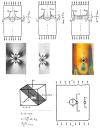
Directions of cracks in the vicinity of a notch in the form of a small drilled hole on the surface where there is (a) uniaxial tension, (b) uniaxial compression, (c) biaxial tension, and (d) biaxial compression. On the right are images of cracks caused by relaxation near the hole in the tensile and compressive regions (own research).
Figure 2
Figure 2
The simplest arrangement of a polariscope for light reflected from the object (own research).
Figure 3
Figure 3
The sequence of colors corresponding to the total orders of isochromy starting from the dark m = 0, through yellow–red–blue–green m = 1, and further through yellow–red–green m = 2, etc., for higher orders (own research).
Figure 4
Figure 4
A professional reflective polariscope placed on a stand along with an example of an isochromic image obtained with its help (own research).
Figure 5
Figure 5
Isochromes in the vicinity of a uniaxially stretched flat bar are seen in sodium lamp light (on the left) and white light (on the right). The middle figures relate to the course of principal stress trajectories and maximum shear stress (own research).
Figure 6
Figure 6
Examples of stress concentrations near a stretched flat bar with a hole (own research).
Figure 7
Figure 7
Compressed model with holes. The direction of greater stress, which is parallel to the contour of the disk, can be clearly seen in the external holes (own research).
Figure 8
Figure 8
Deformations on a thick stress lattice bar during cutting, as well as effects near drilled holes (own research) [15,30].
Figure 9
Figure 9
Isochrome image on a stress lattice casting after spontaneous cracking of a thick bar. The symmetry of the image is noteworthy, registering the deformation of the bent crossbar, the concentration of stresses in the corners, dark isochromes m = 0, and their accumulation near the drilled hole. Next to the lattice is the marked measurement point using the DMS method, which registered smaller deformations than those expected from the cracked section (own research) [15,30].
Figure 10
Figure 10
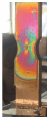
Isochromes on a stretched sample with a double carbide, visible in reflected light. A hole is drilled through the elasto-optic plate on the vertical axis. The obtained image near the hole indicates the direction of higher stress (own research) [15,30].
Figure 11
Figure 11
Isochromes on a stretched disc, visible in reflected light (own research) [15,30].
Figure 12
Figure 12
Diagram of the laser beam path (P–semi-transparent mirror and Z–lenses) (own research).
Figure 13
Figure 13
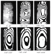
Holograms of the ladle model were obtained using the double exposure method at time intervals described below the photograph (own research).
Figure 14
Figure 14
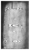
Interference fringes on the surface of the steel ladle model in the initial heating phase. Visible singular points are related to the construction and operational durability of the ladle (own research).

References

    1. Jun T.-S., Korsunsky A.M. Evaluation of residual stresses and strains using the Eigenstrain Reconstruction Method. Int. J. Solids Struct. 2010;47:1678–1686. doi: 10.1016/j.ijsolstr.2010.03.002. - DOI
    1. Rossini N.S., Dassisti M., Benyounis K.Y., Olabi A.G. Methods of measuring residual stresses in components. Mater. Des. 2012;35:572–588. doi: 10.1016/j.matdes.2011.08.022. - DOI
    1. Shet C., Deng X. Residual stresses and strains in orthogonal metal cutting. Int. J. Mach. Tools Manuf. 2003;43:573–587. doi: 10.1016/S0890-6955(03)00018-X. - DOI
    1. Tabatabaeian A., Ghasemi A.R., Shokrieh M.M., Marzbanrad B., Baraheni M., Fotouhi M. Residual Stress in Engineering Materials: A Review. Adv. Eng. Mater. 2022;24:2100786. doi: 10.1002/adem.202100786. - DOI
    1. Wyatt J.E., Berry J.T., Williams A.R. Residual stresses in aluminum castings. J. Mater. Process. Technol. 2007;191:170–173. doi: 10.1016/j.jmatprotec.2007.03.018. - DOI

LinkOut - more resources