

Impact of Temperature Optimization of ITO Thin Film on Tandem Solar Cell Efficiency
- PMID: 38894047
- PMCID: PMC11173995
- DOI: 10.3390/ma17112784
Impact of Temperature Optimization of ITO Thin Film on Tandem Solar Cell Efficiency
Abstract
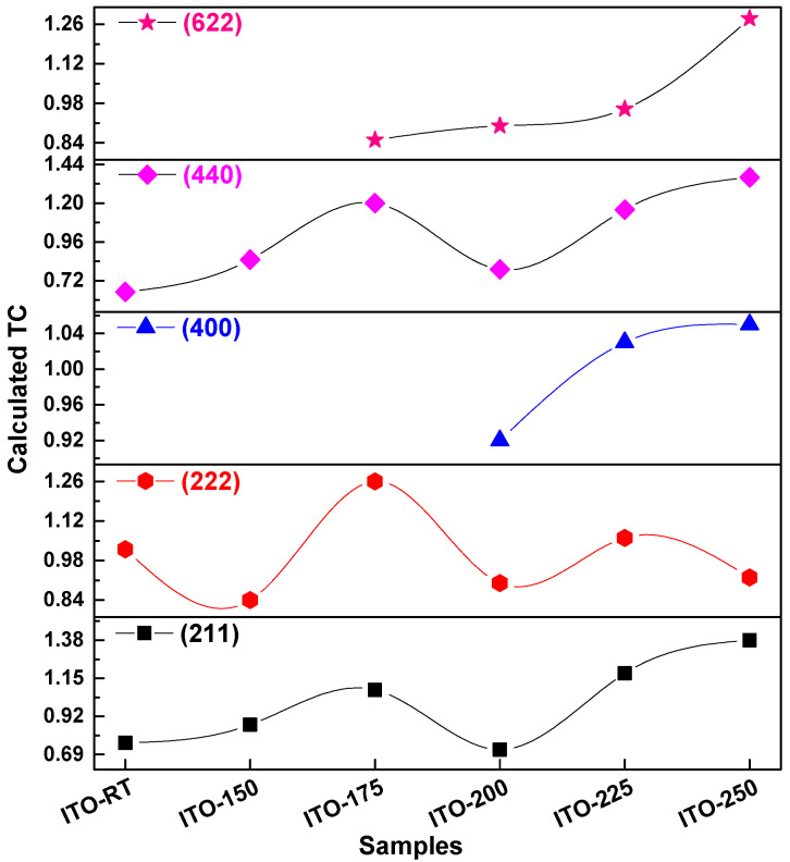
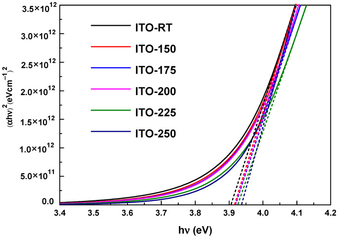
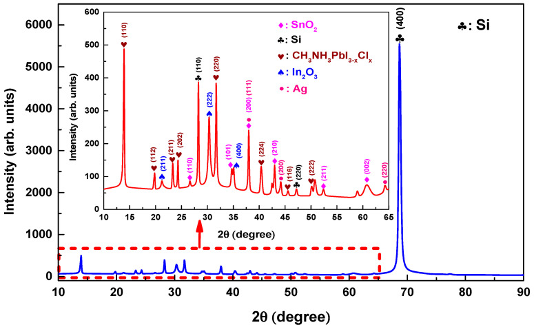
This study examined the impact of temperature optimization on indium tin oxide (ITO) films in monolithic HJT/perovskite tandem solar cells. ITO films were deposited using magnetron sputtering at temperatures ranging from room temperature (25 °C) to 250 °C. The sputtering target was ITO, with a mass ratio of In2O3 to SnO2 of 90% to 10%. The effects of temperature on the ITO film were analyzed using X-ray diffraction (XRD), spectroscopic ellipsometry, and sheet resistance measurements. Results showed that all ITO films exhibited a polycrystalline morphology, with diffraction peaks corresponding to planes (211), (222), (400), (440), and (622), indicating a cubic bixbyite crystal structure. The light transmittance exceeded 80%, and the sheet resistance was 75.1 Ω/sq for ITO deposited at 200 °C. The optical bandgap of deposited ITO films ranged between 3.90 eV and 3.93 eV. Structural and morphological characterization of the perovskite solar cell was performed using XRD and FE-SEM. Tandem solar cell performance was evaluated by analyzing current density-voltage characteristics under simulated sunlight. By optimizing the ITO deposition temperature, the tandem cell achieved a power conversion efficiency (PCE) of 16.74%, resulting in enhanced tandem cell efficiency.
Keywords: deposition temperature; indium tin oxide (ITO); perovskite; silicon heterojunction; tandem solar cell.
Conflict of interest statement
The authors declare no conflicts of interest.
Figures


Similar articles
-
Influence of Oxygen Concentration on the Performance of Ultra-Thin RF Magnetron Sputter Deposited Indium Tin Oxide Films as a Top Electrode for Photovoltaic Devices.Materials (Basel). 2016 Jan 20;9(1):63. doi: 10.3390/ma9010063. Materials (Basel). 2016. PMID: 28787863 Free PMC article.
-
Rapid thermal annealing for high-quality ITO thin films deposited by radio-frequency magnetron sputtering.Beilstein J Nanotechnol. 2019 Jul 25;10:1511-1522. doi: 10.3762/bjnano.10.149. eCollection 2019. Beilstein J Nanotechnol. 2019. PMID: 31431863 Free PMC article.
-
Multicoated Flexible Indium Tin Oxide Electrodes Fabricated Using Magnetron Sputtering and Arc Plasma Ion Plating for Flexible Perovskite Solar Cells.ACS Appl Mater Interfaces. 2024 Sep 11;16(36):47961-47972. doi: 10.1021/acsami.4c12138. Epub 2024 Aug 27. ACS Appl Mater Interfaces. 2024. PMID: 39191509
-
Monolithic Use of Inert Gas for Highly Transparent and Conductive Indium Tin Oxide Thin Films.Nanomaterials (Basel). 2024 Mar 24;14(7):565. doi: 10.3390/nano14070565. Nanomaterials (Basel). 2024. PMID: 38607100 Free PMC article.
-
Indium aluminum nitride: A review on growth, properties, and applications in photovoltaic solar cells.Heliyon. 2024 Nov 14;10(22):e40322. doi: 10.1016/j.heliyon.2024.e40322. eCollection 2024 Nov 30. Heliyon. 2024. PMID: 39650183 Free PMC article. Review.
References
-
- Fraunhofer Institute for Solar Energy Systems. ISE. [(accessed on 17 September 2023)]. Available online: www.cell-to-module.com.
-
- Hafshejani M.T., Keshavarzi R., Mirkhani V., Moghadam M., Tangestaninejad S., Mohammadpoor-Baltork I. Waste Carbon-Based Toner Protection Layer on CsPbBr3 Perovskite Photoanodes for Efficient and Stable Photoelectrochemical Water Oxidation. Int. J. Hydrogen Energy. 2024;59:82–88. doi: 10.1016/j.ijhydene.2024.01.179. - DOI
-
- NREL Best Research-Cell Efficiency Chart. [(accessed on 16 April 2024)]; Available online: www.nrel.gov/pv/cell-efficiency.html.
-
- Richter A., Hermle M., Glunz S.W. Reassessment of the Limiting Efficiency for Crystalline Silicon Solar Cells. IEEE J. Photovolt. 2013;3:1184–1191. doi: 10.1109/JPHOTOV.2013.2270351. - DOI
LinkOut - more resources
Full Text Sources
