Review
. 2024 Jun 6;17(11):2787.
doi: 10.3390/ma17112787.

Bulk MgB2 Superconducting Materials: Technology, Properties, and Applications

Affiliations
Review

Bulk MgB2 Superconducting Materials: Technology, Properties, and Applications

Tetiana Prikhna et al. Materials (Basel). .

Abstract

The intensive development of hydrogen technologies has made very promising applications of one of the cheapest and easily produced bulk MgB2-based superconductors. These materials are capable of operating effectively at liquid hydrogen temperatures (around 20 K) and are used as elements in various devices, such as magnets, magnetic bearings, fault current limiters, electrical motors, and generators. These applications require mechanically and chemically stable materials with high superconducting characteristics. This review considers the results of superconducting and structural property studies of MgB2-based bulk materials prepared under different pressure-temperature conditions using different promising methods: hot pressing (30 MPa), spark plasma sintering (16-96 MPa), and high quasi-hydrostatic pressures (2 GPa). Much attention has been paid to the study of the correlation between the manufacturing pressure-temperature conditions and superconducting characteristics. The influence of the amount and distribution of oxygen impurity and an excess of boron on superconducting characteristics is analyzed. The dependence of superconducting characteristics on the various additions and changes in material structure caused by these additions are discussed. It is shown that different production conditions and additions improve the superconducting MgB2 bulk properties for various ranges of temperature and magnetic fields, and the optimal technology may be selected according to the application requirements. We briefly discuss the possible applications of MgB2 superconductors in devices, such as fault current limiters and electric machines.

Keywords: effect of impurity oxygen; magnesium diboride bulk superconductors; pinning; structural study; superconducting properties.


Conflict of interest statement

The authors declare no conflict of interest.

Figures

Figure 1
Figure 1
Dependences of critical current density (magnetic measurement), Jc, on magnetic field, μoH, for MgB2-based materials at 20 K (a) and 30 K (b) [108]. 1 HP—high-pressure synthesized under 2 GPa at 1050 °C for 1 h from Mg(I):2B(I) with 10% SiC addition; 2 HP—high-pressure synthesized (2 GPa, 1050 °C, 1 h) from Mg(I):2B(I); 3 HP—high-pressure-sintered (2 GPa, 1050 °C, 1 h) from MgB2 (VII); 4 HP—high-pressure-synthesized (2 GPa, 600 °C, 1 h) from Mg (II):2B (II); 5 SPS—spark-plasma-synthesized under 50 MPa at 600 °C for 0.3 h and then at 1050 °C for 0.5 h from Mg(I):2B(III); 6 HotP—synthesized by hot pressing (30 MPa, 900 °C, 1 h) from Mg(I):2B(III) with 10% Ta addition; 7 HIP—synthesized under high isostatic (gas) pressure (0.1 GPa, 900 °C, 1 h) from mixture of Mg(I):2B(III) with 10% Ti addition, which was precompacted into a ring shape by broaching; 8 PL—pressureless sintering (in flowing Ar under 0.1 MPa at 800 °C for 2 h) from mixture of Mg(I):2B(III) with 10% Ti addition, which was precompacted into a ring shape by broaching.
Figure 2
Figure 2
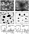
(a,b)—Sample structures obtained by SEM in COMPO (compositional) contrast: (a)—Sample sintered from MgB2 (Type VI) under 2 GPa at 1000 °C for 1 h; bright small zones in (a) seem to be inclusions (containing O, Zr, Nb, and possibly ZrO2) appearing due to milling of initial MgB2. (b)—Structure of sample synthesized from Mg(I):2B(I) under 2 GPa at 800 °C. (c,d)—X-ray patterns of these samples, respectively [109].
Figure 3
Figure 3
Critical current density, Jc, vs. magnetic field, μoH, of MgB2 prepared (a) from Mg(I):2B(III) by SPS under 50 MPa at 600 °C for 0.3 h and then at 1050 °C for 0.5 h and (b) from Mg(I):2B(III) + 10 wt% Ti by HotP under 30 MPa at 1000 °C for 15 min [119].
Figure 4
Figure 4
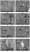
Structures of MgB2 materials prepared from Mg(I):2B(III) mixtures under 50 MPa at 600 °C for 0.5 h and then at 1050 °C for 0.5 h. Images were obtained using SEM at different magnifications [109]; (ac)—SEI and, (d)—BEI.
Figure 5
Figure 5
Real (m’) part of the ac susceptibility (magnetic moment) vs. temperature, T [108]. Small samples for the study were cut from superconductors prepared under 2 GPa. 1—edge of block 63 mm in diameter, prepared from Mg(I):2B (I and III) + 2 wt% Ti, at 800 °C; 2—center of the same block; 3—block 63 mm in diameter, Mg(I):2B(III) at 950 °C, 4—tablet 9 mm in diameter, Mg(I):2B(V) + 10 wt% Ti, at 1050 °C; 5—tablet 9 mm in diameter, Mg(I):2B(III) + 10 wt% Ti, at 800 °C; 6—tablet 9 mm in diameter, Mg(I):2B(III) + 10 wt% Ti at 1050 °C; 7—tablet 9 mm in diameter, Mg(I):2B(III) + 10 wt% Ta, at 1050 °C; 8—tablet 9 mm in diameter, Mg(II):2B(II) at 600 °C.
Figure 6
Figure 6
Thermal dependence of the upper critical magnetic field, Bc2, of bulk MgB2 [120,132], prepared from: 1—Mg(II):2B(II) under 2 GPa (HP) at 600 °C for 1 h; 2—Mg(I):2B(III) (30 MPa (HotP), 800 °C, 2h); 3—Mg(I):2B(III) (50 MPa (SPS), at 600 °C for 0.3 h and then at 1050 °C for 0.5 h); 4—Mg(I):2B(III) (2 GPa (HP), 900 °C, 1 h); 5—Mg(I):2B(V) + 10 wt% Zr (2 GPa (HP), 800 °C, 1 h); 6—Mg(I):2B(V) + 10 wt% Ti (2 GPa (HP), 800 °C, 1 h); 7—Mg(I):2B(I) + 10 wt% SiC (2 GPa (HP), 1050 °C, 1 h).
Figure 7
Figure 7
(ad)—Microstructures obtained by SEM at different magnifications of MgB2 material prepared from Mg(II):2B(II) mixtures under 2 GPa at 600 °C for 1 h [109]. (a)—SEI and, (bd)—BEI.
Figure 8
Figure 8
The dependences of critical current density, Jc, at 20 K on a magnetic field. The MgB2 samples were prepared from Mg(I):2B(I) and Mg(I):2B(III). The graph was composed using the data presented in [20,98,103,119].
Figure 9
Figure 9
(a,b)—SEM images in SEI mode of MgB2 materials synthesized from Mg(I):2B(III) mixtures under 2 GPa, for 1 h at 800 and 1050 °C, respectively [109]. (c,d)—Schema of MgB2-based material structures synthesized at low temperature of 800 °C (e) and high temperature of 1050 °C (f) [85]. (e,f)—X-ray patterns of samples shown in (a,b) [113].
Figure 10
Figure 10
Critical current density, Jc, vs. magnetic field, µoH, of MgB2 materials prepared from Mg(I):2B(I) and Mg(I):2B(III) mixtures under 2 GPa, at 800 and 1050 °C for 1 h (a,b), respectively; additions of SiC (0.2–0.8 μm) to Mg(I):2B(I) mixture (c) and Ti (99%, 1–3 μm) to Mg(I):2B(III) (d) [103].
Figure 11
Figure 11
(a) Maximal pinning forces, BFp(max), and corresponding values of magnetic fields at 20 K vs. synthesis pressure for MgB2-based materials synthesized from Mg(I) and B(III) at 800 (circles) and 1050 °C (stars); (b)—normalized pinning force, Fp, vs. magnetic field, B, calculated from the critical current density, Jc; and (c)—dependence of critical current density, Jc, on magnetic field. Designations: k = Bpeak/Bn; PP—point pinning; GBP—grain boundary pinning; and MP—mixed pinning [128]. Curves: (1) Mg(I):2B(I) + 10% SiC, 2GPa, 1050 °C, 1 h, k = 0.51 (PP); (2) Mg(I):2B(III) + 10% Ti, 2 GPa, 1050 °C, 1 h, k = 0.42 (MP); (3) Mg(I):2B(III), 50 MPa, 600 °C for 0.3 h and then 1050 °C for 0.5 h, k = 0.63 (>PP?); (4) Mg(II):2B(II) with 3.5% C, 2 GPa, 600 °C, 1 h, k = 0.31 (GBP); (5) Mg(I):2B(III) + 10% Ti, 30 MPa for 1 h and then 1000 °C for 0.2 h, k = 0.42 (MP); (6) MgB2, 16 MPa, 1150 °C, 0.3 h, k = 0.45 (PP); (7) Mg(I):2B(III), in flowing Ar atmosphere under 0.1 MPa, 800 °C, 4 h, k = 0.35 (GBP).
Figure 12
Figure 12
(a)—X-ray patterns of the material synthesized under 2 GPa at 1200 °C for 1 h from Mg(I):12B(III); (b)—dependences of Jc on the external magnetic fields, μoH, at 20 K for the materials synthesized under 2 GPa for 1 h from Mg(I) and B(III), taken in the ratio Mg:xB, and synthesized at temperature, TS: curves 1—Mg:12B, TS = 1200 °C; curve 2—Mg:10B, TS = 1200 °C; curve 3—Mg:8B, TS = 1200 °C; curve 4—Mg:6B, TS = 1200 °C; curve 5—Mg:4B, TS = 1200 °C; curve 6—Mg:12B, TS = 800 °C; curve 7—Mg:20B, TS = 1200 °C; (c)—backscattering SEM image of the material prepared under 2 GPa at 1200 °C for 1 h from Mg(I):12B(III); (d) HRT—EM microstructure (of a MgB12 grain, the stoichiometry of which was estimated by HRTEM EDX); (e)—dependences of critical current density, Jc, on magnetic fields, μoH, at 10–35 K for the materials prepared under 2 GPa at 1200 °C for 1 h from mixtures of Mg(I):8B(III) [103].
Figure 13
Figure 13
Microstructures of the materials synthesized from Mg(I):B(III) with a 10 wt% of Ti (3–10 μm) addition under 2 GPa for 1 h at 800 (a,c) and 1050 °C (b,d) [108]. X-ray patterns of these materials (e,f). (c,d) show the places where Ti is absent [103,113].
Figure 14
Figure 14
(a) Image of microstructure of MgB2 sample with 10 wt% of Ti (3–10 μm); image 16a was taken in the place where the Ti grains are absent. (bd)—EDX maps of boron, oxygen, and magnesium distributions over the area of the image shown in 16e (the brighter the area looks, the higher the amount of the element under study) [103].
Figure 15
Figure 15
(ac) SEM images of MgB2 sample with 10 wt% of Ti powder (about 60 μm) synthesized under 2 GPa at 800 °C for 1 h: SEI (ac) [113]. Notations: “I”—Mg-B-O inclusions, MgBx—higher magnesium borides. In (c), the points marked by No. 1–6 are the points for which were made quantitative Auger analyses, the results of which are summarized in Table 6 [113].
Figure 16
Figure 16
(a,b)—Microstructure of magnesium diboride synthesized from Mg(I):B(III) with 10 wt% TiH2 addition under 2 GPa at 950 °C for 1 h in SEI [84] (a) and COMPO (b) regimes.
Figure 17
Figure 17
Microstructure of materials with 10 wt% of SiC additions (0.2–0.8 μm) prepared from Mg(I):2B(I) under 2 GPa (HP) at 800 °C for 1 h (ad) and at 1050 °C (eh); (a,c,e,g)—SEI images; (b,d,f,h)—COMPO images; (a,b), (c,d), (e,f), and (g,h) are paired images of the same place under the same magnification but in different modes—SEI and COMPO [132].
Figure 18
Figure 18
Characteristics of MgB2-based materials synthesized from Mg(I):2B(III) and Mg(II):2B(II) under 2 GPa for 1 h at different temperatures: (af)—dependences of critical current density, Jc, on magnetic field, B, of materials without (a) and with additions of titanium (Ti) (b,e), polyvalent titanium oxides (Ti-O) (c,f), and titanium carbide (TiC) (d); (g)—fields of irreversibility, Birr, and (h) upper critical magnetic fields, BC2, vs. temperature [85].
Figure 19
Figure 19
(a)—X-ray diffraction pattern, (b)—dependence of critical current densities, Jc, on magnetic field, µoH, at 10, 20, 25, 30, 33, and 35 K of the material, prepared from Mg(I):2B(I) under 2 GPa at 1050 °C for 1 h [117].
Figure 20
Figure 20
Calculated density of electronic states, N(E), for MgB2 (a), MgB1.75O0.25 (b), MgB1.5O0.5 (c) per formula unit; (d)—calculated DOS at the Fermi level. N(EF) depends on the oxygen concentration, x, in MgB2-xOx compounds (hollow squares). The total DOS and partial contributions of Mg, B, and O atoms are indicated by solid squares, solid triangles, and solid circles, respectively [132].
Figure 21
Figure 21
(a)—Dependence of the binding energy, Eb, on the oxygen concentration, x, in MgB2-xOx/Cx: 1, 3—homogeneous oxygen and carbon substitutions of boron atoms, respectively; 2, 4—the lowest binding energy vs. x for the ordered oxygen and carbon substitutions (for example, in nearby positions or in pairs), respectively. (b)—Z-contrast image of coherent oxygen-containing inclusions in [010] of MgB2 obtained using HRTEM (high–resolution transmission microscopy). Bright atoms—Mg. The contrast increases in each second row and is due to the presence of oxygen in each second boron plane. The white arrows show the columns of atoms in which oxygen is present [117].
Figure 22
Figure 22
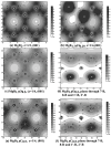
Maps of electron density distribution for: (a)—MgB2 (z = 1/2, (001)), (b)—MgB1.75O0.25 (z = 1/4, (001) [108]), (c)—MgB1.5O0.5 (z = 1/4, (001)); z-coordinates of the plane of a 2 × 2 × 2 supercell, where z is given in units of the c parameter of a 2 × 2 × 2 MgB2 supercell [132]; (d)—MgB1.5O0.5 in the transversal plane under an angle to the basal boron planes of the hexagonal unit cell to show the boron plane without imbedded oxygen atoms together with the Mg plane (the plane goes through the 7-B, 8-B, and 1′-B, 2′-B positions of a 2 × 2 × 2 supercell [132]); (e)—MgB1.5C0.5 (z = 1/4, (001)); (f)—MgB1.5C0.5 in the transversal plane under an angle to the basal boron planes (the plane goes through the 7-B, 8-B, and 1′-B, 2′-B positions of a 2 × 2 × 2 supercell) [117].
Figure 23
Figure 23
Examples of MgB2 bulk superconductors: (a)—obtained using HotP, (b) [120], (c) —obtained using HP and then the rings were cut mechanically, and (d)—obtained by machining a bulk cylinder manufactured using SPS [26].
Figure 24
Figure 24
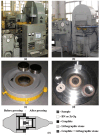
High quasi-hydrostatic pressing (HP) in ISM NASU. Hydraulic 140 MN-effort press from the ASEA company (a), hydraulic 25 MN-effort press (b), cylinder piston high–pressure apparatus (HPA) (c), recessed-anvil type (HPA) for 25 MN press (d), and scheme of high–pressure cell of the recessed-anvil HPA (before and after loading) (e).
Figure 25
Figure 25
Hydraulic press DO 630 for hot pressing with generator and inductor (a,b); general view of inductor of hot press during heating (shining window—opening for temperature estimation by pyrometer) (c), scheme of assembled inductor (d).
Figure 26
Figure 26
Installation for spark plasma sintering (a) and, scheme of SPS heating chamber (b) [166].
Figure 27
Figure 27
(a)—The schemes of an SFCL model and a testing circuit for the simulation of a fault event. (b)—Typical oscilloscope traces of the current in a protected circuit (black, solid curve) and the voltage drop across the primary coil of the SFCL model (red, dashed curve) at 50 Hz and about 4 K (from [90]). The experiment details are described in [120]. “A”—is ammeter.
Figure 28
Figure 28
General view of azebra-type rotor of a 1300W/215V superconducting motor with MgB2 bulk superconductor [9].
Figure 29
Figure 29
(a) Magnetic shield of MgB2 in the shape of a cup (outer radius, Ro = 10.15 mm; inner radius, Ri =7.0 mm; external height, he = 22.5 mm; internal depth, di = 18.3 mm). The material is machinable by chipping. The shielding factors (i.e., the ratio between an outer applied magnetic field, Happl, and an inner magnetic field measured by a Hall sensor at different z1–z5 positions (b)) at T = 30 K are shown in (c). The dashed lines represent the shielding factors computed in correspondence with the Hall probe positions, assuming the magnetic field dependence of Jc(B) at 30 K. (Figure 2 in [26] adapts the results obtained in [159]).

Similar articles

Cited by

References

    1. Koblischka-Veneva A., Koblischka M.R., Berger K., Nouailhetas Q., Douine B., Muralidhar M., Murakami M. Comparison of Temperature and Field Dependencies of the Critical Current Densities of Bulk YBCO, MgB2, and Iron-Based Superconductors. IEEE Trans. Appl. Supercond. 2019;29:1–5. doi: 10.1109/TASC.2019.2900932. - DOI
    1. Erbe M., Hänisch J., Freudenberg T., Kirchner A., Mönch I., Kaskel S., Schultz L., Holzapfel B. Improved REBa2Cu3O7−x (RE = Y, Gd) structure and superconducting properties by addition of acetylacetone in TFA-MOD precursor solutions. J. Mater. Chem. A. 2014;2:4932–4944. doi: 10.1039/C3TA15243J. - DOI
    1. Briant C.L., Hall E.L., Lay K.W., Tkaczyk I.E. Microstructural evolution of the BSCCO-2223 during powder-in-tube processing. J. Mater. Res. 1994;9:2789–2808. doi: 10.1557/JMR.1994.2789. - DOI
    1. Beales T.P., Jutson J., Le Lay L., Mölgg M. Comparison of the powder-in-tube processing properties of two (Bi2-xPbx)Sr2Ca2Cu3O10+δ powders. J. Mater. Chem. 1997;7:653–659. doi: 10.1039/A606896K. - DOI
    1. Ballarino A. HTS Materials for LHC Current Leads. [(accessed on 23 November 2005)]. Available online: https://at-mel-cf.web.cern.ch/html/HTS_materials.htm.

LinkOut - more resources