

Instability Compensation of Recording Interferometer in Phase-Sensitive OTDR
- PMID: 38894131
- PMCID: PMC11174648
- DOI: 10.3390/s24113338
Instability Compensation of Recording Interferometer in Phase-Sensitive OTDR
Abstract
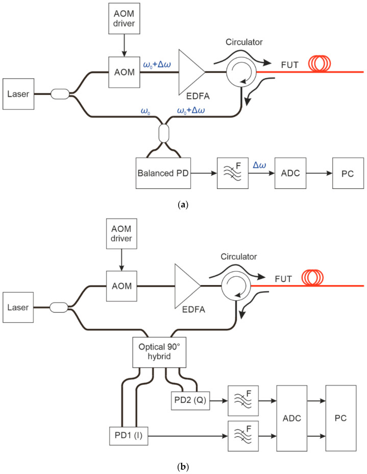
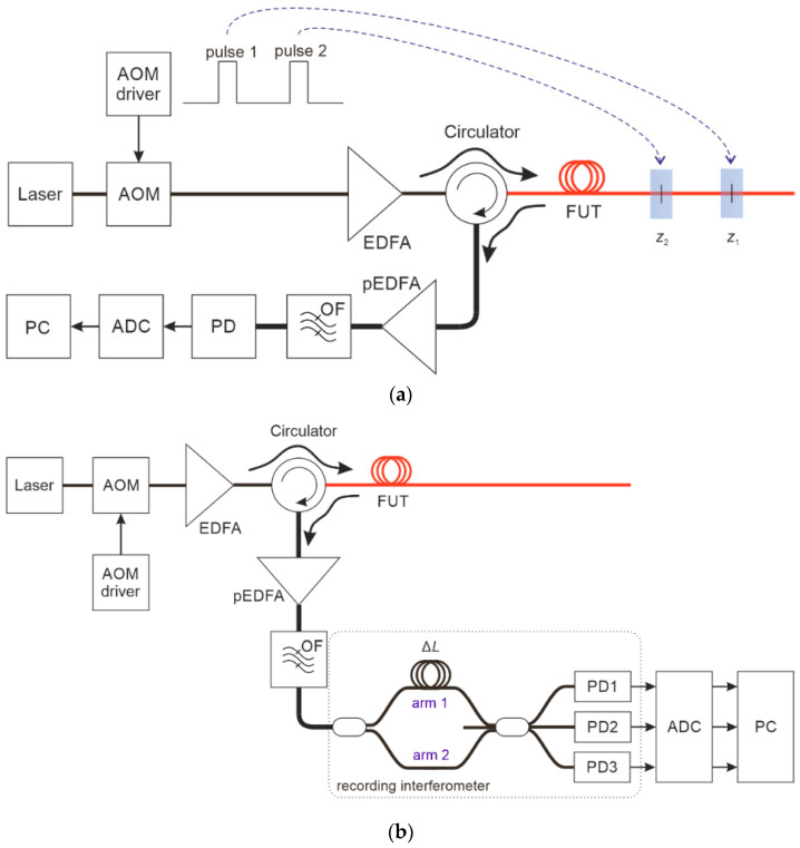
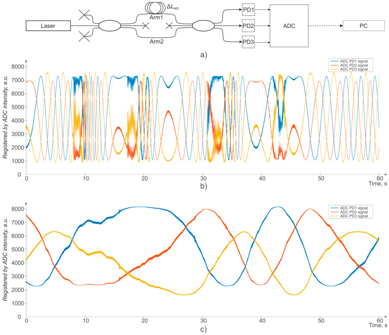
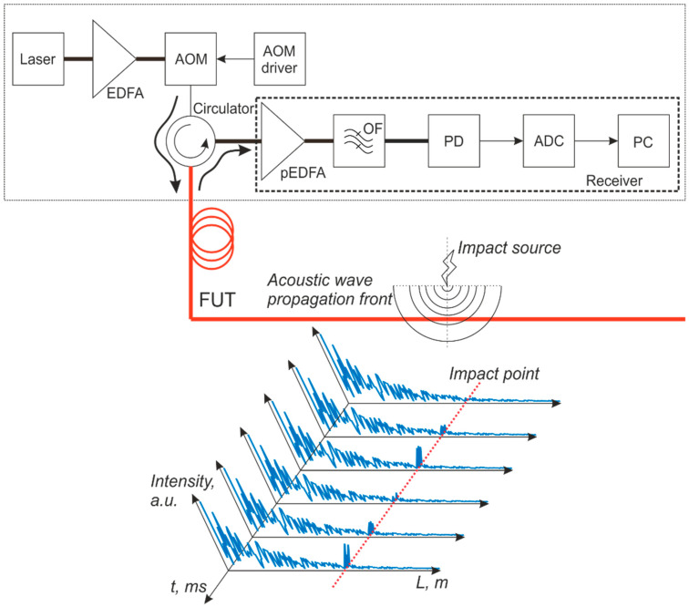
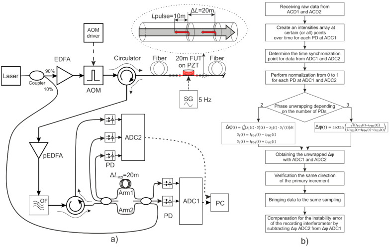
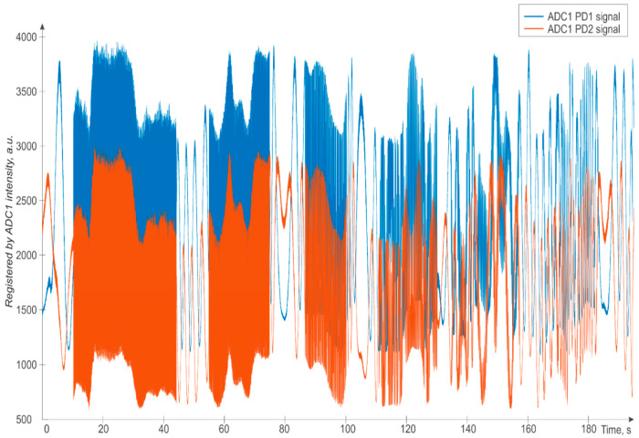
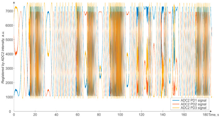
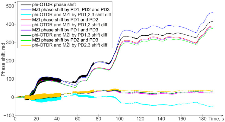
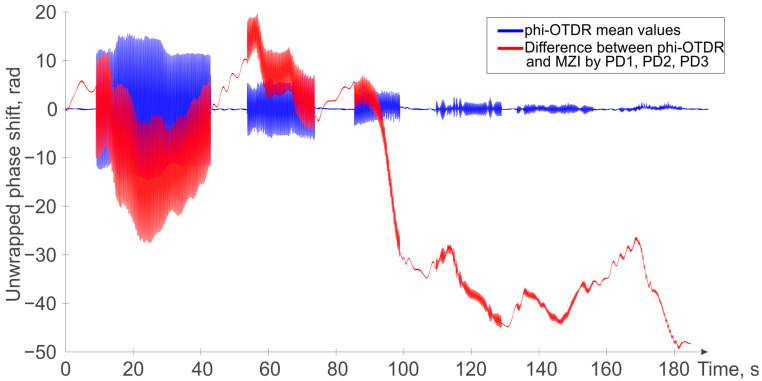
In the paper, a new method of phase measurement error suppression in a phase-sensitive optical time domain reflectometer is proposed and experimentally proved. The main causes of phase measurement errors are identified and considered, such as the influence of the recording interferometer instabilities and laser wavelength instability, which can cause inaccuracies in phase unwrapping. The use of a Mach-Zender interferometer made by 3 × 3 fiber couplers is proposed and tested to provide insensitivity to the recording interferometer and laser source instabilities. It is shown that using all three available photodetectors of the interferometer, instead of just one pair, achieves significantly better accuracy in the phase unwrapping. A novel compensation scheme for accurate phase measurements in a phase-sensitive optical time domain reflectometer is proposed, and a comparison of the measurement signals with or without such compensation is shown and discussed. The proposed method, using three photodetectors, allows for very good compensation of the phase measurement errors arising from common-mode noise from the interferometer and laser source, providing a significant improvement in signal detection. In addition, the method allows the tracking of slow temperature changes in the monitored fiber/object, which is not obtainable when using a simple low-pass filter for phase unwrapping error reduction, as is customary in several systems of this kind.
Keywords: acoustic monitoring; distributed fiber optic sensor; fiber optic sensor; phase-sensitive OTDR; weak fiber Bragg gratings (WFBG).
Conflict of interest statement
The authors declare no conflicts of interest. The funders had no role in the design of the study; in the collection, analyses, or interpretation of data; in the writing of the manuscript; or in the decision to publish the results.
Figures
References
-
- Kersey A.D. A review of recent developments in fiber optic sensor technology. Opt. Fiber Technol. 1996;2:291–317. doi: 10.1006/ofte.1996.0036. - DOI
-
- Udd E. An overview of fiber-optic sensors. Rev. Sci. Instrum. 1995;66:4015–4030. doi: 10.1063/1.1145411. - DOI
-
- Grattan K.T.V., Sun T. Fiber optic sensor technology: An overview. Sens. Actuators A Phys. 2000;82:40–61. doi: 10.1016/S0924-4247(99)00368-4. - DOI
-
- Francis T.S., Yin S. Fiber Optic Sensors. Marcel Dekker Inc.; New York, NY, USA: 2002.
-
- Culshaw B., Kersey A. Fiber-optic sensing: A historical perspective. J. Lightw. Technol. 2008;26:1064–1078. doi: 10.1109/JLT.0082.921915. - DOI
Grants and funding
LinkOut - more resources
Full Text Sources
