. 2024 May 28;24(11):3467.
doi: 10.3390/s24113467.

MCML-BF: A Metal-Column Embedded Microstrip Line Transmission Structure with Bias Feeders for Beam-Scanning Leakage Antenna Design

Affiliations

MCML-BF: A Metal-Column Embedded Microstrip Line Transmission Structure with Bias Feeders for Beam-Scanning Leakage Antenna Design

Shunhu Hou et al. Sensors (Basel). .

Abstract

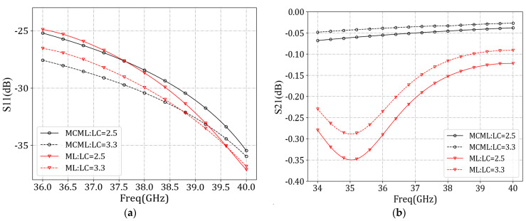
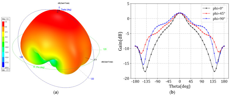
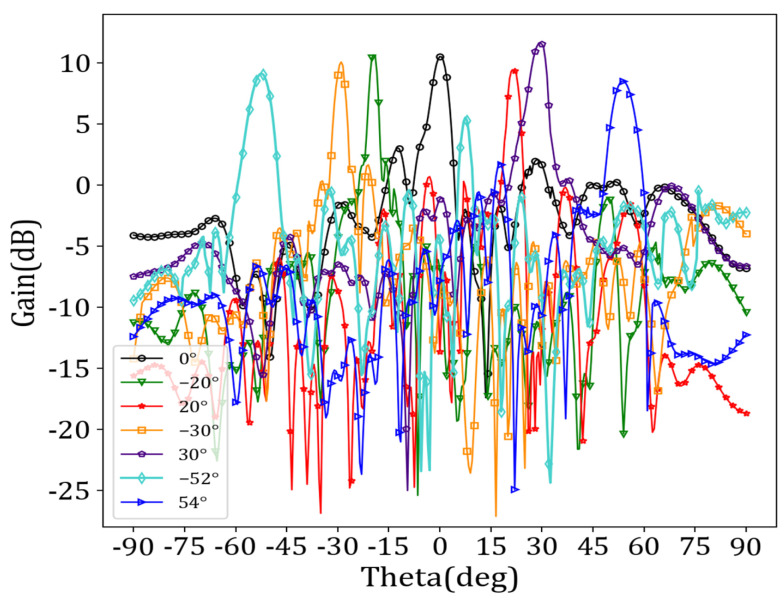
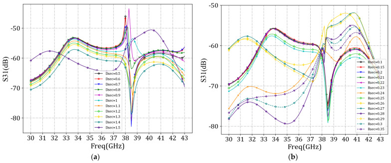
This article proposes a novel fixed-frequency beam scanning leakage antenna based on a liquid crystal metamaterial (LCM) and adopting a metal column embedded microstrip line (MCML) transmission structure. Based on the microstrip line (ML) transmission structure, it was observed that by adding two rows of metal columns in the dielectric substrate, electromagnetic waves can be more effectively transmitted to reduce dissipation, and attenuation loss can be lowered to improve energy radiation efficiency. This antenna couples TEM mode electromagnetic waves into free space by periodically arranging 72 complementary split ring resonators (CSRRs). The LC layer is encapsulated in the transmission medium between the ML and the metal grounding plate. The simulation results show that the antenna can achieve a 106° continuous beam turning from reverse -52° to forward 54° at a frequency of 38 GHz with the holographic principle. In practical applications, beam scanning is achieved by applying a DC bias voltage to the LC layer to adjust the LC dielectric constant. We designed a sector-blocking bias feeder structure to minimize the impact of RF signals on the DC source and avoid the effect of DC bias on antenna radiation. Further comparative experiments revealed that the bias feeder can significantly diminish the influence between the two sources, thereby reducing the impact of bias voltage introduced by LC layer feeding on antenna performance. Compared with existing approaches, the antenna array simultaneously combines the advantages of high frequency band, high gain, wide beam scanning range, and low loss.

Keywords: beam scanning; bias feeder; holographic principle; liquid crystal; periodic leakage antenna.


Conflict of interest statement

The authors declare no conflict of interest.

Figures

Figure 1
Figure 1
The antenna cell structure. (a) Main view; (b) Top view; (c) left view.
Figure 2
Figure 2
Electric and magnetic field energy distribution at the CSRR slot. (a) Electric field energy distribution; (b) Magnetic field energy distribution.
Figure 3
Figure 3
Comparison of MCML and ML performance after removing the CSRR slot. (a) S11 parameters; (b) S21 parameters.
Figure 4
Figure 4
Comparison of electromagnetic wave transmission between MCML and ML structures. (a) ML electric field energy map; (b) MCML electric field energy map; (c) ML electric field vector map; (d) MCML electric field vector map.
Figure 5
Figure 5
MCML cell performance simulation. (a) S11 parameters; (b) S21 parameters.
Figure 6
Figure 6
Dispersion curve of antenna unit.
Figure 7
Figure 7
Radiation diagrams of MCML cell. (a) 3D plot; (b) 2D plot.
Figure 8
Figure 8
Structure of the periodic leakage antenna array.
Figure 9
Figure 9
Beam gain maps corresponding to different beam directions.
Figure 10
Figure 10
Reflection coefficients corresponding to different beam directions.
Figure 11
Figure 11
Bias feeder structure.
Figure 12
Figure 12
Comparison curves of S31 parameters under different wbias values.
Figure 13
Figure 13
Comparison curves of S31 parameters under different dbias values.
Figure 14
Figure 14
Sector-blocking bias feeder structure.
Figure 15
Figure 15
Comparison curves of S31 parameters under different dsec and rsec values. (a) dsec; (b) rsec.
Figure 16
Figure 16
Beam gain diagrams corresponding to different beam directions after adding bias feeder.
Figure 17
Figure 17
Reflection coefficients corresponding to different beam directions after adding bias feeder.

References

    1. Shen F., Hu Q., Gong C. Determining the Antenna Phase Center for the High-Precision Positioning of Smartphones. Sensors. 2024;24:2243. doi: 10.3390/s24072243. - DOI - PMC - PubMed
    1. Wei D., Zhang P. A Linearly and Circularly Polarization-Reconfigurable Leaky Wave Antenna Based on SSPPs-HSIW. Electronics. 2023;12:2602. doi: 10.3390/electronics12122602. - DOI
    1. Menzione F., Paonni M. 3D Galileo Reference Antenna Pattern for Space Service Volume Applications. Sensors. 2024;24:2220. doi: 10.3390/s24072220. - DOI - PMC - PubMed
    1. Al-Gburi A.J.A., Zakaria Z., Alsariera H., Akbar M.F., Ibrahim I.M., Ahmad K.S., Al-Bawri S.S. Broadband circular polarised printed antennas for indoor wireless communication systems: A comprehensive review. Micromachines. 2022;13:1048. doi: 10.3390/mi13071048. - DOI - PMC - PubMed
    1. Ushikoshi D., Higashiura R., Tachi K., Fathnan A.A., Mahmood S., Takeshita H., Wakatsuchi H. Pulse-driven self-reconfigurable meta-antennas. Nat. Commun. 2023;14:633. doi: 10.1038/s41467-023-36342-1. - DOI - PMC - PubMed

LinkOut - more resources