

Optimizing Capacitive Pressure Sensor Geometry: A Design of Experiments Approach with a Computer-Generated Model
- PMID: 38894295
- PMCID: PMC11175090
- DOI: 10.3390/s24113504
Optimizing Capacitive Pressure Sensor Geometry: A Design of Experiments Approach with a Computer-Generated Model
Abstract
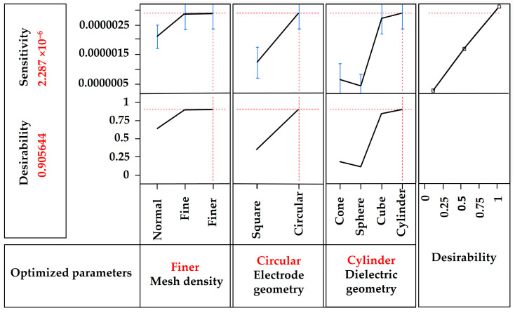
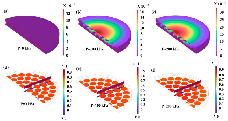
This study presents a comprehensive investigation into the design and optimization of capacitive pressure sensors (CPSs) for their integration into capacitive touch buttons in electronic applications. Using the Finite Element Method (FEM), various geometries of dielectric layers were meticulously modeled and analyzed for their capacitive and sensitivity parameters. The flexible elastomer polydimethylsiloxane (PDMS) is used as a diaphragm, and polyvinylidene fluoride (PVDF) is a flexible material that acts as a dielectric medium. The Design of Experiment (DoE) techniques, aided by statistical analysis, were employed to identify the optimal geometric shapes of the CPS model. From the prediction using the DoE approach, it is observed that the cylindrical-shaped dielectric medium has better sensitivity. Using this optimal configuration, the CPS was further examined across a range of dielectric layer thicknesses to determine the capacitance, stored electrical energy, displacement, and stress levels at uniform pressures ranging from 0 to 200 kPa. Employing a 0.1 mm dielectric layer thickness yields heightened sensitivity and capacitance values, which is consistent with theoretical efforts. At a pressure of 200 kPa, the sensor achieves a maximum capacitance of 33.3 pF, with a total stored electric energy of 15.9 × 10⁻¹² J and 0.468 pF/Pa of sensitivity for 0.1 dielectric thickness. These findings underscore the efficacy of the proposed CPS model for integration into capacitive touch buttons in electronic devices and e-skin applications, thereby offering promising advancements in sensor technology.
Keywords: PDMS; PVDF; capacitive pressure sensor; design of experiment; dielectrics; optimization; sensitivity.
Conflict of interest statement
The authors declare no conflicts of interest.
Figures


Similar articles
-
Highly Sensitive Porous PDMS-Based Capacitive Pressure Sensors Fabricated on Fabric Platform for Wearable Applications.ACS Sens. 2021 Mar 26;6(3):938-949. doi: 10.1021/acssensors.0c02122. Epub 2021 Mar 17. ACS Sens. 2021. PMID: 33728910
-
Highly Sensitive and Flexible Capacitive Pressure Sensors Based on Vertical Graphene and Micro-Pyramidal Dielectric Layer.Nanomaterials (Basel). 2023 Feb 11;13(4):701. doi: 10.3390/nano13040701. Nanomaterials (Basel). 2023. PMID: 36839069 Free PMC article.
-
Printed and Flexible Capacitive Pressure Sensor with Carbon Nanotubes based Composite Dielectric Layer.Micromachines (Basel). 2019 Oct 23;10(11):715. doi: 10.3390/mi10110715. Micromachines (Basel). 2019. PMID: 31652696 Free PMC article.
-
Capacitive Based Micromachined Resonators for Low Level Mass Detection.Micromachines (Basel). 2020 Dec 25;12(1):13. doi: 10.3390/mi12010013. Micromachines (Basel). 2020. PMID: 33375651 Free PMC article. Review.
-
Advancements in and Research on Coplanar Capacitive Sensing Techniques for Non-Destructive Testing and Evaluation: A State-of-the-Art Review.Sensors (Basel). 2024 Aug 1;24(15):4984. doi: 10.3390/s24154984. Sensors (Basel). 2024. PMID: 39124031 Free PMC article. Review.
Cited by
-
Analysis of Polymer-Ceramic Composites Performance on Electrical and Mechanical Properties through Finite Element and Empirical Models.Materials (Basel). 2024 Aug 2;17(15):3837. doi: 10.3390/ma17153837. Materials (Basel). 2024. PMID: 39124501 Free PMC article.
References
-
- Dong C., Bai Y., Zou J., Cheng J., An Y., Zhang Z., Li Z., Lin S., Zhao S., Li N. Nondestructive Testing and Evaluation. Taylor and Francis Ltd.; Oxford, UK: 2024. Flexible capacitive pressure sensor: Material, structure, fabrication and application. - DOI
-
- Hu Z., Chu Z., Chen G., Cui J. Design of Capacitive Pressure Sensors Integrated with Anisotropic Wedge Microstructure-Based Dielectric Layer. IEEE Sensors J. 2023;23:21040–21049. doi: 10.1109/jsen.2023.3300702. - DOI
-
- Khan S.M., Mishra R.B., Qaiser N., Hussain A.M., Hussain M.M. Diaphragm shape effect on the performance of foil-based capacitive pressure sensors. AIP Adv. 2020;10:015009. doi: 10.1063/1.5128475. - DOI
-
- Singh V., Singh B. PDMS/PVDF-MoS2 based flexible triboelectric nanogenerator for mechanical energy harvesting. Polymer. 2023;274:125910. doi: 10.1016/j.polymer.2023.125910. - DOI
-
- Chen J., Zheng J., Gao Q., Zhang J., Zhang J., Omisore O.M., Wang L., Li H. Polydimethylsiloxane (PDMS)-based flexible resistive strain sensors for wearable applications. Appl. Sci. 2018;8:345. doi: 10.3390/app8030345. - DOI
LinkOut - more resources
Full Text Sources
