. 2024 Sep;11(34):e2402818.
doi: 10.1002/advs.202402818. Epub 2024 Jun 19.

Microconfined Assembly of High-Resolution and Mechanically Robust EGaIn Liquid Metal Stretchable Electrodes for Wearable Electronic Systems

Affiliations

Microconfined Assembly of High-Resolution and Mechanically Robust EGaIn Liquid Metal Stretchable Electrodes for Wearable Electronic Systems

Jingxuan Ma et al. Adv Sci (Weinh). 2024 Sep.

Abstract

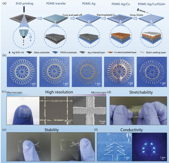
Stretchable electrodes based on liquid metals (LM) are widely used in human-machine interfacing, wearable bioelectronics, and other emerging technologies. However, realizing the high-precision patterning and mechanical stability remains challenging due to the poor wettability of LM. Herein, a method is reported to fabricate LM-based multilayer solid-liquid electrodes (m-SLE) utilizing electrohydrodynamic (EHD) printed confinement template. In these electrodes, LM self-assembled onto these high-resolution templates, assisted by selective wetting on the electrodeposited Cu layer. This study shows that a m-SLE composed of PDMS/Ag/Cu/EGaIn exhibits line width of ≈20 µm, stretchability of ≈100%, mechanical stability ≈10 000 times (stretch/relaxation cycles), and recyclability. The multi-layer structure of m-SLE enables the adjustability of strain sensing, in which the strain-sensitive Ag part can be used for non-distributed detection in human health monitoring and the strain-insensitive EGaIn part can be used as interconnects. In addition, this study demonstrates that near field communication (NFC) devices and multilayer displays integrated by m-SLEs exhibit stable wireless signal transmission capability and stretchability, suggesting its applicability in creating highly-integrated, large-scale commercial, and recyclable wearable electronics.

Keywords: electrodeposition; electrohydrodynamic printing; flexible electronics; liquid metal; multilayer circuits.


Conflict of interest statement

The authors declare no conflict of interest.

Figures

Figure 1
Figure 1
Fabrication and structures of m‐SLE. a) Schematic illustration of fabrication process involving EHD printing, transfer, electrodeposition, and EGaIn selectively wetting. b) Corresponded optical images at each step. Demonstration of m‐SLE with c) high resolution, d) stretchability, e) adhesion ability and f) conductivity.
Figure 2
Figure 2
EHD printing of Ag pattern and representative m‐SLE patterns. a) Schematic diagram of EHD printing mechanism of Taylor cone generation. b) Finite element simulation of electric field intensity during Taylor cone generation. Parameter optimization of EHD printing, including c) voltages, d) working heights, e) printing speeds and f) printing layers. g) Representative m‐SLE patterns prepared with optimized EHD printing parameters, including horseshoe curves, serpentine curves, rhombic grids, square grids and third‐order Hilbert curves. h) Grid patterns on horseback, a glass tube and inclined surfaces.
Figure 3
Figure 3
Microstructures of m‐SLE. SEM images of m‐SLE fabrication at different stages, namely a) PDMS‐Ag, b) PDMS‐Ag/Cu and c) PDMS‐Ag/Cu/EGaIn (m‐SLEs). d) Cross‐sectional SEM image of m‐SLE. e–i) EDS mapping of m‐SLE. j) Schematic diagram of PDMS‐Ag in stretching state. SEM images of PDMS‐Ag in k) initial, l) stretching and m) release state. n) Schematic diagram of m‐SLE in stretching state. SEM images of m‐SLE in o) initial, p) stretching and q) release state.
Figure 4
Figure 4
Sensing properties of PDMS‐Ag and m‐SLE based strain sensor. a) Resistive response of PDMS‐Ag with different line widths (20, 40, 60 µm). b) Resistive response of m‐SLE with different line widths (20, 40, 60 µm). c) Resistive response of PDMS‐Ag and m‐SLE strain sensors with different line widths under cyclic load strains of 10%, 20%, 30%, and 40% respectively. d) Resistive response of PDMS‐Ag‐20 and m‐SLE‐20 strain sensors under a series of stepwise increasing strains from 10% to 50%. e) Resistive response of PDMS‐Ag‐20 and m‐SLE‐20 strain sensors when applying and releasing 10% strain. f) Resistive response of PDMS‐Ag strain sensor at different frequencies (0.02. 0.04, 0.08, 0.16, 0.32 Hz) and strains (0.25%, 0.5%, 1.0%, 1.5%, 2.0%). g) Cycling stability of m‐SLE sensor at 100% strain within 10 000 cycles. The insets show the first and last 20 cycles respectively. h) Comparison of the resolution, number of functional layers, and cycling stability with reported literature.[ 53 , 54 , 55 , 56 , 57 , 58 , 59 , 60 , 61 , 62 , 63 , 64 , 65 ]
Figure 5
Figure 5
The wearable m‐SLE strain sensors for human health monitoring. a) Schematic illustration of the composition of the finger joint strain sensor. b) Optical image of the finger joint strain sensor. Optical images showing c) the initial state, d) bending of the first joint (Motion A) and e) bending of the second joint (Motion B) of thumb. f) Resistance changes of a strain sensor mounted on the thumb during cyclic bending of the first and second joints. The red arrow (Motion A) and the blue arrow (Motion B) represent the time points of bending of the first joint and the second joint respectively. Resistance changes during health monitoring in different parts of the human body, namely g) throat, h) nose breathing, i) mouth breathing, j) pulse, k) smile, l) index finger bending, m) wrist bending and n) knee bending.
Figure 6
Figure 6
Application of m‐SLE in NFC antenna and E‐skin display array and its recycling strategy. a) Fabrication of an m‐SLE‐based NFC antenna, which enables wireless interaction with a smartphone, harnessing its energy to light up LEDs. b) Photograph of m‐SLE‐based NFC antenna. Optical images of NFC tags under c) small and d) large bends and the corresponding strain distribution under bending (inset). e) The photograph that shows the power transmitted from an NFC‐enabled smartphone to an m‐SLE‐based NFC antenna can light up 19 parallel‐connected LEDs. f) Schematic illustration of m‐SLE‐based E‐skin display array. g) Schematic layout of the m‐SLE‐based E‐skin display array. h) Optical image of the m‐SLE‐based E‐skin display array. i) E‐skin display array applying to human wrist. j) The display shows the letters “H”, “I”, “T” and the numbers “1”, “2”, “3”. k) Recycling strategy of EGaIn in m‐SLE‐based flexible devices.

References

    1. Li M., Zhang Y., Lian L., Liu K., Lu M., Chen Y., Zhang L., Zhang X., Wan P., Adv. Funct. Mater. 2022, 32, 2208141.
    1. Wen F., Sun Z., He T., Shi Q., Zhu M., Zhang Z., Li L., Zhang T., Lee C., Adv. Sci. 2020, 7, 2000261. - PMC - PubMed
    1. Zhu M., Sun Z., Zhang Z., Shi Q., He T., Liu H., Chen T., Lee C., Sci. Adv. 2020, 6, eaaz8693. - PMC - PubMed
    1. Choi H. J., Ahn J., Jung B. K., Choi Y. K., Park T., Bang J., Park J., Yang Y., Son G., Oh S. J., ACS Appl. Mater. Interfaces 2023, 15, 42836. - PubMed
    1. Park S., Heo S. W., Lee W., Inoue D., Jiang Z., Yu K., Jinno H., Hashizume D., Sekino M., Yokota T., Fukuda K., Tajima K., Someya T., Nature 2018, 561, 516. - PubMed

LinkOut - more resources