. 2024 Oct;92(4):1584-1599.
doi: 10.1002/mrm.30148. Epub 2024 Jun 20.

Multiphoton simultaneous multislice imaging

Affiliations

Multiphoton simultaneous multislice imaging

Tanya Deniz Ipek et al. Magn Reson Med. 2024 Oct.

Abstract

Purpose: To develop multiphoton excitation techniques for simultaneous multislice (SMS) imaging and evaluate their performance and specific absorption rate (SAR) benefit. To improve multiphoton SMS reconstruction quality with a novel CAIPIRINHA (controlled aliasing in parallel imaging results in higher acceleration) design.

Theory and methods: When a conventional single-slice RF field is applied together with an oscillating gradient field, the two can combine to generate multiphoton excitation at multiple discrete spatial locations. Because the conventional RF is reused at multiple spatial locations, multiphoton excitation offers reduced SAR for SMS applications. CAIPIRINHA shifts are often used to improve parallel-imaging acceleration. Interestingly, CAIPIRINHA-type shifts can be obtained for multiphoton SMS by updating the oscillating gradient phase at every phase encode. In this work, both a gradient-echo and a spin-echo sequence with multiphoton CAIPIRINHA-SMS excitation pulses are implemented for in vivo human imaging at 3 T.

Results: For three slices, multiphoton SMS provides a 51% reduction in SAR compared with conventional superposition SMS, whereas for five slices, SAR is reduced by 66%. Multiphoton SMS outperforms PINS (power independent of number of slices) and MultiPINS in terms of SAR reduction especially when the pulse duration is short, slices are thin, and/or the slice spacing is large. A custom CAIPIRINHA phase-encoding design for multiphoton SMS significantly improves reconstruction quality.

Conclusion: Multiphoton SMS excitation can be obtained by combining conventional single-slice RF pulses with an oscillating gradient and offers significant SAR benefits compared with conventional superposition SMS. A novel CAIPIRINHA design allows higher multiband factors for multiphoton SMS imaging.

Keywords: CAIPIRINHA; MultiPINS; PINS; SAR; SMS; multiphoton.


Conflict of interest statement

Conflicts of Interest

CL and VH are inventors of patent Application US17/664,799 related to multiphoton MRI.

Figures

Figure 1.
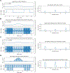
Figure 1.. Multiphoton SMS Excitation with Oscillating Gradients.
A) Amplitude and phase of an xy-polarized single-slice SLR RF pulse. B) An oscillating gradient waveform generated by adding a sinusoidal gradient on top of the regular slice-select gradient. C) Slice profiles resulting from the multiphoton excitation pulses shown in A and B. Center slice has one-photon excitation, hence, there are no z-photons in resonance (m=0). Left slice has two-photon excitation with one z-photon being emitted (m=1). Right slice also has two-photon excitation but with one z-photon being absorbed (m=1). D) Energy level diagrams corresponding to the slice profiles in C. For the center slice, the frequency of the photons of xy-RF match the local resonance frequency (Larmor frequency) and one-photon excitation occurs. For the side slices, the single-slice xy-RF combines with the non-uniform z-RF field generated by oscillating gradients to excite two-photon resonances.
Figure 2.
Figure 2.. Flip Angle Equalization Simulations for a Three-Slice Multiphoton SMS Design.
A) Amplitude and phase of a scaled-down (c0=0.429) xy-polarized single-slice SLR RF pulse are shown on the left. Corresponding slice profiles are shown on the right. Unequal transverse magnetization amplitudes of the simultaneously excited slices indicate unequal flip angles caused by the lower efficiency of two-photon excitation. B) On the left is a scaled-down (c1=0.512), frequency-modulated and right-shifted version of the single-slice SLR RF pulse that achieves effective one-photon excitation for the right slice. Corresponding slice profiles are shown on the right. C) On the left is a scaled-down (c1=0.512), frequency-modulated and left-shifted version of the single-slice SLR RF pulse that achieves effective one-photon excitation for the left slice. Corresponding slice profiles are shown on the right. D) Summation of the RF pulses in A, B, and C are shown on the left and resulting slice profiles indicating equal flip angles are shown on the right. Scaling coefficients are chosen to obtain equal transverse magnetization amplitudes.
Figure 3.
Figure 3.. Multiphoton SMS and One-Photon SMS Excitation Pulses with Identical Slice Profiles.
A) Amplitude and phase of the xy-polarized multiphoton SMS RF pulse that generates equal flip angles for all slices. B) Multiphoton SMS oscillating gradient waveform. C) Multiphoton SMS slice profiles resulting from the combination of the excitation pulses in A and B. D) Amplitude and phase of the xy-polarized one-photon SMS RF pulse that generates excitation identical to that generated by the RF pulse in A. The higher amplitude of the one-photon RF pulse indicates the higher power deposition of one-photon SMS relative to multiphoton SMS. Quantitatively, multiphoton SMS reduces SAR by 51% for three simultaneously excited slices. E) One-photon SMS slice-select gradient waveform. F) One-photon SMS slice profiles resulting from the combination of the excitation pulses in D and E. Identical slice profiles in C and F show that multiphoton SMS and one-photon SMS can achieve equivalent excitation.
Figure 4.
Figure 4.. CAIPIRINHA Phase Encoding for a Three-Slice Multiphoton SMS Design.
A) Amplitude and phase of an xy-polarized single-slice SLR RF pulse. B) Oscillating gradient waveforms with different phases. For a three-slice SMS design, to shift the left slice up and right slice down by FOV/3, the gradient phase is increased by 2π/3 at every phase encode resulting in three different gradient waveforms. C) k-space lines acquired using different oscillating gradients. At every phase encode, we cycle through the gradients shown in B to create a phase cycling pattern for the simultaneously excited slices. D) Resulting image with the side slices shifted up and down by FOV/3 and the center slice left unshifted.
Figure 5.
Figure 5.. Flip Angle Equalization Experiments for a Three-Slice Multiphoton SMS Design.
A) Aliased and disentangled sagittal slices acquired with our multiphoton SMS gradient-echo sequence with flip angle equalization. Flip angles are equalized using the process outlined in Figure 2. Disentangled slices demonstrate similar brightness levels indicating equal flip angles. B) Single-slice reference scans acquired individually with a conventional gradient-echo sequence. C) Aliased and disentangled sagittal slices acquired with our multiphoton SMS gradient-echo sequence without flip angle equalization. Due to the lower efficiency of multiphoton excitation, side slices which experience two-photon excitation look darker than the center slice which has one-photon excitation.
Figure 6.
Figure 6.. CAIPIRINHA Phase Encoding Improves Reconstruction Quality for Multiphoton SMS Images.
A) Aliased and disentangled sagittal slices acquired with a multiphoton SMS gradient-echo sequence with CAIPIRINHA phase encoding. B) Aliased and disentangled sagittal slices acquired with a multiphoton SMS gradient-echo sequence without CAIPIRINHA phase encoding. When CAIPIRINHA shifts are not utilized, separated slices show elevated levels of noise as shown in the zoomed-in regions of the center slice.
Figure 7.
Figure 7.. Five Slices Can Be Simultaneously Excited with Multiphoton SMS Imaging When the Coil Geometry Is Suitable.
A) Aliased and disentangled sagittal slices acquired with a multiphoton SMS gradient-echo sequence using a 12-channel GE head and neck receiver array. The coil geometry of this receiver array does not provide enough information to separate five closely spaced sagittal slices and the disentangled slices have elevated noise levels and significant aliasing artifacts. B) Aliased and disentangled slices acquired with a multiphoton SMS gradient-echo sequence using a 15-channel flexible head cap array. The wearable receiver array has a coil geometry more suitable for closely spaced sagittal slices and provides higher SNR. Zoomed-in regions of disentangled slices show acceptable noise levels and reduced/fully removed aliasing artifacts. These receiver arrays produce images with different dynamic ranges and the images acquired with the flexible coil saturate if they are carried to the same dynamic range as the GE coil. For a fair comparison, the brightness levels of the zoomed-in regions were adjusted to be on a similar level.
Figure 8.
Figure 8.. T1 and T2 Contrast Demonstration with a Multiphoton SMS Spin-Echo Sequence.
A) Three sagittal slices acquired with a T1-weighted multiphoton SMS spin-echo sequence. B) Three sagittal slices acquired with a T2-weighted multiphoton SMS spin-echo sequence.
Figure 9.
Figure 9.. Multiphoton SMS Achieves More SAR Reduction than PINS and MultiPINS Especially for Shorter Total RF Pulse Durations, Thinner Slices, and/or Larger Slice Spacings.
Each subplot shows how SAR reduction percentage relative to conventional superposition SMS changes with the total RF pulse duration for a specific choice of slice thickness and spacing. The number of simultaneously excited slices is chosen to be 3 for a slice spacing of 3.5 cm, whereas it is chosen to be 5 for a slice spacing of 2 cm. The legend in B applies to all subplots. A) SAR reduction percentages for a slice spacing of 3.5 cm and a slice thickness of 1 mm. B) SAR reduction percentages for a slice spacing of 3.5 cm and a slice thickness of 2 mm. C) SAR reduction percentages for a slice spacing of 2 cm and a slice thickness of 1 mm. D) SAR reduction percentages for a slice spacing of 2 cm and a slice thickness of 2 mm. Multiphoton SMS outperforms PINS and MultiPINS in terms of SAR reduction when the total RF pulse duration is shorter and when the slices are thinner and farther apart.

References

    1. Abragam A. The Principles of Nuclear Magnetism. Repr. Clarendon Pr; 1986.
    1. Michal CA. Nuclear magnetic resonance noise spectroscopy using two-photon excitation. J Chem Phys. 2003;118(8):3451–3454. doi: 10.1063/1.1553758 - DOI
    1. Eles PT, Michal CA. Two-photon two-color nuclear magnetic resonance. J Chem Phys. 2004;121(20):10167–10173. doi: 10.1063/1.1808697 - DOI - PubMed
    1. Eles PT, Michal CA. Two-photon excitation in nuclear magnetic and quadrupole resonance. Prog Nucl Magn Reson Spectrosc. 2010;56(3):232–246. doi: 10.1016/j.pnmrs.2009.12.002 - DOI - PubMed
    1. Brunner DO, Pavan M, Dietrich BE, Rothmund D, Heller A, Prüssmann KP. Sideband Excitation for Concurrent RF Transmission and Reception. In Proceedings of the 19th Annual Meeting of ISMRM, Montreal, Canada, 2011. Abstract 0625.