. 2024 Jun 13;14(6):140.
doi: 10.3390/membranes14060140.

Network Derivation of Liquid Junction Potentials in Single-Membrane System

Affiliations

Network Derivation of Liquid Junction Potentials in Single-Membrane System

Andrzej Ślęzak et al. Membranes (Basel). .

Abstract

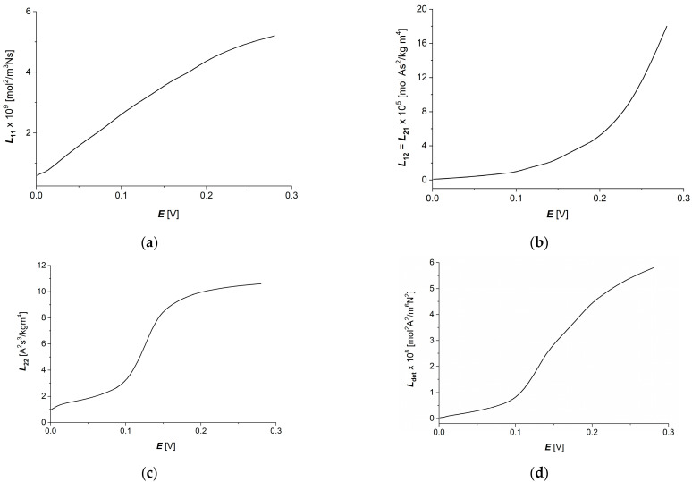
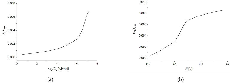
Peusner's network thermodynamics (PNT) is one of the more important formalisms of nonequilibrium thermodynamics used to describe membrane transport and the conversion of the internal energy of the system into energy dissipated in the environment and free energy used for the work involved in the transport of solution components in membrane processes. A procedure of transformation the Kedem-Katchalsky (K-K) equations for the transport of binary electrolytic solutions through a membrane to the Kedem-Katchalsky-Peusner (K-K-P) equations based on the PNT formalism for liquid junction potentials was developed. The subject of the study was a membrane used for hemodialysis (Ultra Flo 145 Dialyser) and aqueous NaCl solutions. The research method was the L version of the K-K-P formalism for binary electrolyte solutions. The Peusner coefficients obtained from the transformations of the K-K formalism coefficients for the transport of electrolyte solutions through the artificial polymer membrane were used to calculate the coupling coefficients of the membrane processes and to calculate the dissipative energy flux. In addition, the dissipative energy flux, as a function of thermodynamic forces, made it possible to investigate the energy conversion of transport processes in the membrane system.

Keywords: Kedem–Katchalsky–Peusner equations; Peusner transport coefficients; S entropy; internal energy conversion; membrane transport; polymeric membrane.


Conflict of interest statement

The authors declare no conflicts of interest.

Figures

Figure 1
Figure 1
Two-port L representation of the phenomenological equations in which forces (X1, X2) controlling flow sources (J1, J2) are placed in parallel with conductances (L11 and L22) [14,16].
Figure 2
Figure 2
Model of a single-membrane system: M—membrane; Ch and Cl—NaCl solution concentrations (Ch > Cl); Js—solute flux; I—electric ionic current; Eh and El—electrode potentials.
Figure 3
Figure 3
Practical representation of the phenomenological liquid junction potential equations: (a) G=κ; (b) G=ωsCs.
Figure 4
Figure 4
Image of the Ultra Flo 145 Dialyzer membrane obtained by a scanning microscope (Zeiss Supra 35) at 10,000× magnification.
Figure 5
Figure 5
Dependencies κ=f(π/Cs)E=0.15 V. (a), τc=f(π/Cs)E=0.15 V. (b), κ=f(E)π/Cs=6.64kJ/mol (c) and τc=f(E)π/Cs=6.64kJ/mol (d) for Ultra Flo 145 Dialyzer membrane and aqueous NaCl solutions.
Figure 6
Figure 6
Graphic illustration of dependencies Lij=f(πs/Cs)E=0.15 V (i,j ∈ {1, 2}) and Ldet=f(πs/Cs)E=0.15 V for aqueous NaCl solutions: (a) L11=f(πs/Cs)E=0.15 V; (b) L12=L21=f(πs/Cs)E=0.15 V; (c) L22=f(πs/Cs)E=0.15 V; (d) Ldet=f(πs/Cs)E=0.15 V.
Figure 7
Figure 7
Graphic illustration of dependencies Lij=f(Eπ/Cs=6.64kJ/mol), (i,j ∈ {1, 2}) and Ldet=f(Eπ/Cs=6.64kJ/mol), for aqueous NaCl solutions: (a) L11=f(E, πs/Cs = 6.64 kJ/mol), (b) L12=L21=f(E,πs/Cs = 6.64 kJ/mol) (c) L22=f(E, πs/Cs = 6.64 kJ/mol) and (d) Ldet=f(E, πs/Cs = 6.64 kJ/mol).
Figure 8
Figure 8
Graphic illustration of dependencies l12=l21=f(πs/Cs,E=0.15 V) (a), l12=l21=f(E,πs/Cs=6.64 kJ/mol) (b), QL=f(πs/Cs,E=0.15 V) (c) and QL=f(E,π/Cs=6.64 kJ/mol) (d) for aqueous NaCl solutions.
Figure 9
Figure 9
Graphic illustration of dependencies (eL)max=f(πs/Cs,E=0.15 V) (a) and (eL)max=f(E, πs/Cs = 6.64 kJ/mol) (b) for aqueous NaCl solutions.
Figure 10
Figure 10
Graphic illustration of dependencies (ΦS)LE=const=f(πs/Cs) (a) and (ΦS)Lπs/Cs=const=f(E) (b) for aqueous NaCl solutions.
Figure 11
Figure 11
Graphic illustration of dependencies (ΦF)L12E=const=f(πs/Cs) (a), (ΦU)L12E=const=f(πs/Cs) (c), (ΦF)L12πs/Cs=const=f(E) (b) and (ΦU)L12πs/Cs=const=f(E) (d) for aqueous NaCl solutions.

References

    1. Baker R. Membrane Technology and Application. John Wiley & Sons; New York, NY, USA: 2012.
    1. Radu E.R., Voicu S.I., Thakur V.K. Polymeric membranes for biomedical applications. Polymers. 2023;15:619. doi: 10.3390/polym15030619. - DOI - PMC - PubMed
    1. Dorotkiewicz-Jach A., Markowitz P., Rachuna J., Arabski M., Drulis-Kawa Z. The impact of agarose immobilization on the activity of lytic Pseudomonas araginosa phages combined with chemicals. Appl. Microbiol. Biotechnol. 2023;107:897–913. doi: 10.1007/s00253-022-12349-4. - DOI - PMC - PubMed
    1. Zhang Y., Yu L., Zhang X.-D., Wang Y.-H., Yang C., Liu X., Wang W.-P., Zhang Y., Li X.-T., Li G., et al. A smart risk-responding polymer membrane for safer batteries. Sci. Adv. 2023;9:eade5802. doi: 10.1126/sciadv.ade5802. - DOI - PMC - PubMed
    1. Bolto B., Zhang J., Wu X., Xie Z. A review on current development of membranes for oil removal from wastewaters. Membranes. 2020;10:65. doi: 10.3390/membranes10040065. - DOI - PMC - PubMed

LinkOut - more resources