. 2024 Jul 9;121(28):e2303648121.
doi: 10.1073/pnas.2303648121. Epub 2024 Jul 1.

Growing three-dimensional objects with light

Affiliations

Growing three-dimensional objects with light

Gabriel Lipkowitz et al. Proc Natl Acad Sci U S A. .

Abstract

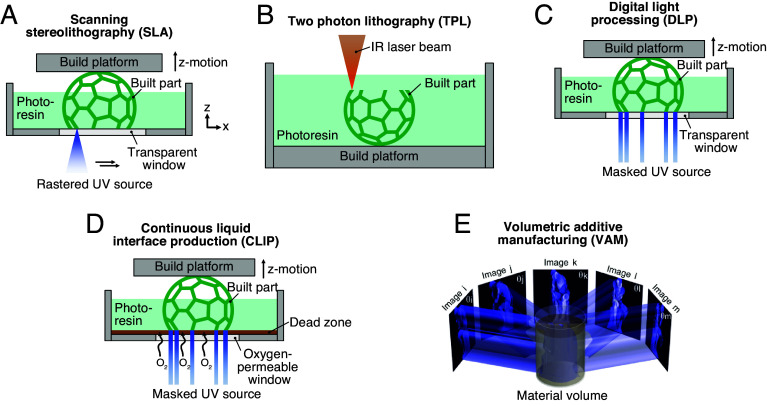
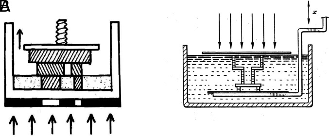
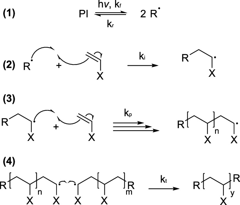
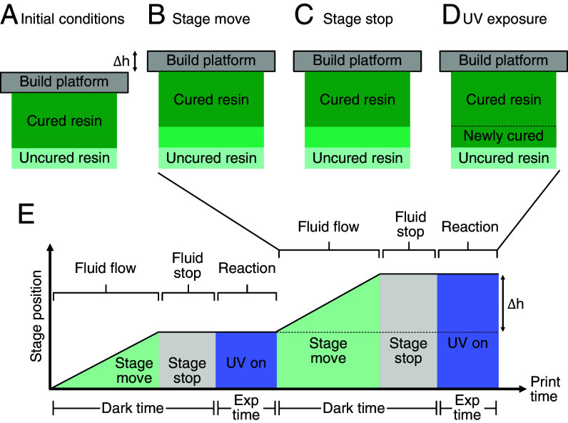
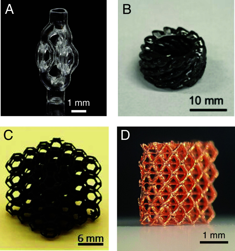
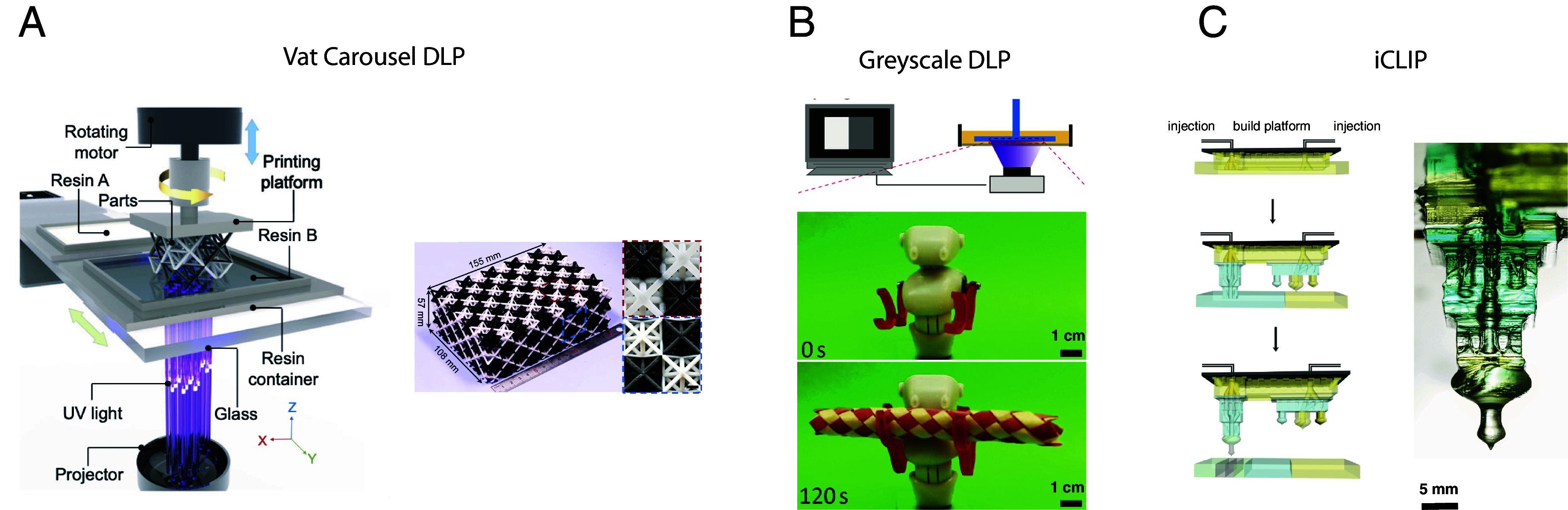
Vat photopolymerization (VP) additive manufacturing enables fabrication of complex 3D objects by using light to selectively cure a liquid resin. Developed in the 1980s, this technique initially had few practical applications due to limitations in print speed and final part material properties. In the four decades since the inception of VP, the field has matured substantially due to simultaneous advances in light delivery, interface design, and materials chemistry. Today, VP materials are used in a variety of practical applications and are produced at industrial scale. In this perspective, we trace the developments that enabled this printing revolution by focusing on the enabling themes of light, interfaces, and materials. We focus on these fundamentals as they relate to continuous liquid interface production (CLIP), but provide context for the broader VP field. We identify the fundamental physics of the printing process and the key breakthroughs that have enabled faster and higher-resolution printing, as well as production of better materials. We show examples of how in situ print process monitoring methods such as optical coherence tomography can drastically improve our understanding of the print process. Finally, we highlight areas of recent development such as multimaterial printing and inorganic material printing that represent the next frontiers in VP methods.

Keywords: 3D printing; additive manufacturing; computational fabrication.


Conflict of interest statement

Competing interests statement:J.M.D. declares that he has an equity stake in Carbon Inc. and M.A.P. and J.R.T. declare that they are employees of Carbon, Inc., which is a venture-backed start-up company that owns related U.S. Patent 9,040,090, U.S. Patent 9,216,546, U.S. Patent 9,360,757, and others. M.A.S. advises 3D Architech, a VP-based metal 3D printing company. J.M.D., M.A.P., and J.R.T. declare that they have an equity stake in Carbon, Inc. due to current or previous employment at Carbon Inc. J.M.D. declares that he is an inventor on related U.S. Patent 9,040,090, U.S. Patent 9,216,546, U.S. Patent 9,360,757, and others. G.L., I.A.C., and J.M.D. declare that they are named co-inventors in methods for multimaterial iCLIP and related pending patent applications. J.M.D. declares that his lab at Stanford is sponsored by the Wellcome Leap Foundation and the Bill and Melinda Gates Foundation. J.M.D. declares, that as a co-founder, board member, and former CEO, and as an active researcher in additive manufacturing, that he has had hundreds of social media and journalist interviews about Carbon and additive manufacturing.

Figures

Fig. 1.
Fig. 1.
Schematic of AM methods. Schematics of common VP techniques including (A) scanning stereolithography, (B) two photon lithography, (C) digital light projection, (D) continuous liquid interface production, and (E) volumetric AM, specifically computed axial lithography, adapted with permission from ref. . Support structures may be needed for some techniques but are omitted for clarity.
Fig. 2.
Fig. 2.
Schematics from Kodama’s and Hull’s pioneering works. (A) Schematic from Kodama’s 1981 work depicting bottom–up projection of 2D image into resin vat. Adapted with permission from ref. . Copyright 1981 American Institute of Physics. (B) Schematic from Hull’s 1984 patent, in which photopatterning is controlled by a masked and collimated UV light source. Adapted from ref. .
Fig. 3.
Fig. 3.
Scheme of photoinitiated radical chain-growth polymerization. 1) A photoinitiator (PI) is homolytically cleaved to form radicals. 2) Initiation of polymerization by a radical. 3) Propagation of a radical across a double bond leading to polymerization. 4) Termination due to combination of two propagating chains.
Fig. 4.
Fig. 4.
Factors that affect CLIP speed specifically include chemical kinetics, fluid dynamics, and supporting machine movement. (A) Initially, the build platform is stationary and uncured resin is quiescent. (B) The stage moves a layer thickness Δh. (C) After moving the prescribed layer height, the stage stops, and the resin settles. (D) Once the resin is again quiescent, UV exposure cures a new layer of resin. (E) Coordinated stage movement and UV exposure as a function of time. Adapted from ref. .
Fig. 5.
Fig. 5.
Photoinduced free radical polymerization with acrylate monomers and oxygen inhibition. Interaction of UV light with a photoinitiator generates radicals that initiate free radical photopolymerization to define the shape of a 3D printed part. In acrylate-based resins, dissolved oxygen in the resin must be consumed before gelation can occur. In CLIP (pictured) additional oxygen is delivered to a thin region near the window known as the dead zone, preventing resin from curing on the window.
Fig. 6.
Fig. 6.
Thermal control with a mobile interface. Infrared camera images of prints (A) without a mobile interface and (B) with a mobile interface show a reduction in accumulated heat during printing when incorporating a mobile interface that can convectively remove heat. Figure adapted with permission from ref. .
Fig. 7.
Fig. 7.
OCT enables in situ observation of resin dynamics. (A) Schematic of OCT measurement during printing. The OCT scanner and UV light source converge at a spot in the resin bath where polymerization occurs. (B) A representative OCT image during printing of a cylinder. Image analysis enables flow fields to be ascertained. (C) Analytical solution of flow fields in the dead zone using the lubrication theory approximation, where z~ and r~ are vertical and radial position in dead zone, respectively, and |vr~| is radial velocity.
Fig. 8.
Fig. 8.
OCT imaging of liquid window interface. Images of (A) a part printed above a resin–immiscible liquid and (B) the same process when the immiscible liquid has been degassed.
Fig. 9.
Fig. 9.
Inorganic VP materials. (A) Glass fabricated with volumetric AM. Adapted with permission from ref. . (B) Pyrolytic carbon fabricated via projection-based VP. Adapted with permission from ref. . (C) Silicon oxycarbide ceramic fabricated via projection stereolithography. Adapted with permission from ref. . (D) Copper metal fabricated via hydrogel infusion of gels produced using projection stereolithography (98, 103).
Fig. 10.
Fig. 10.
Multimaterial VP techniques. (A) Vat carousel DLP, adapted from ref. , (B) Grayscale DLP, adapted from ref. , and (C) Injection CLIP, adapted from ref. .

References

    1. Pagac M., et al. , A review of vat photopolymerization technology: Materials, applications, challenges, and future trends of 3D printing. Polymers 13, 1–20 (2021). - PMC - PubMed
    1. Lewis J. A., Direct ink writing of 3D functional materials. Adv. Funct. Mater. 16, 2193–2204 (2006).
    1. Ziaee M., Crane N. B., Binder jetting: A review of process, materials, and methods. Addit. Manuf. 28, 781–801 (2019).
    1. King W. E., et al. , Laser powder bed fusion additive manufacturing of metals: Physics, computational, and materials challenges. Appl. Phys. Rev. 2, 041304 (2015).
    1. Panetta J., et al. , Elastic textures for additive fabrication. ACM Trans. Graphics 34, 1–12 (2015).

LinkOut - more resources