. 2024 Jul;21(216):20240141.
doi: 10.1098/rsif.2024.0141. Epub 2024 Jul 3.

Bio-inspired compensatory strategies for damage to flapping robotic propulsors

Affiliations

Bio-inspired compensatory strategies for damage to flapping robotic propulsors

M L Hooper et al. J R Soc Interface. 2024 Jul.

Abstract

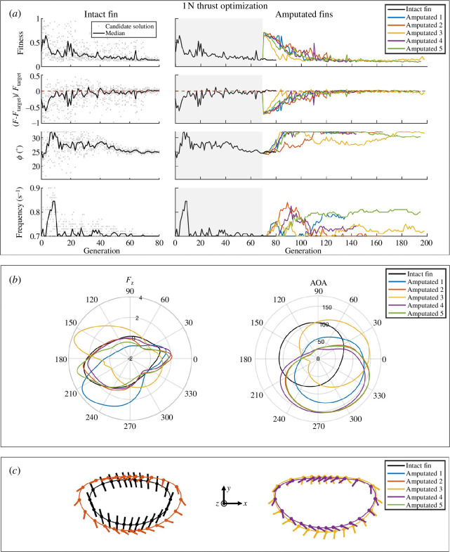
Natural swimmers and flyers can fully recover from catastrophic propulsor damage by altering stroke mechanics: some fish can lose even 76% of their propulsive surface without loss of thrust. We consider applying these principles to enable robotic flapping propulsors to autonomously repair functionality. However, direct transference of these alterations from an organism to a robotic flapping propulsor may be suboptimal owing to irrelevant evolutionary pressures. Instead, we use machine learning techniques to compare these alterations with those optimal for a robotic system. We implement an online artificial evolution with hardware-in-the-loop, performing experimental evaluations with a flexible plate. To recoup thrust, the learned strategy increased amplitude, frequency and angle of attack (AOA) amplitude, and phase-shifted AOA by approximately 110°. Only amplitude increase is reported by most fish literature. When recovering side force, we find that force direction is correlated with AOA. No clear amplitude or frequency trend is found, whereas frequency increases in most insect literature. These results suggest that how mechanical flapping propulsors most efficiently adjust to damage may not align with natural swimmers and flyers.

Keywords: covariance matrix adaptation evolutionary strategy; evolutionary algorithm; flapping propulsion; propulsor damage; self-repairing functionality; stroke mechanics.


Conflict of interest statement

We declare we have no competing interests.

Figures

Views of the experimental set-up and parameters.
Figure 1.
Views of the experimental set-up and parameters. Subfigure (a) shows the fin attached to the SPM and submerged inside the oil tank. Subfigure (b) is a visual representation of the stroke angle (φ), thickness angle (ψ), camber (λ), rotation angle (χ) and sections I–IV corresponding to the speed code. The trajectory is viewed from the underside of the fin (i.e. positive z out of the page). The fin, shown by a solid line intersecting the elliptical trajectory, moves counterclockwise passing through points I, II, III and IV in order. (c) defines the coordinate system used in this work; the x-, y- and z-coordinates are all defined in the laboratory frame. The normal coordinate, denoted ‘n’, is normal to the plane defined by a fully rigid fin. The two types of flexible fins, intact and amputated, are shown in (d).
PIV plane and sample image. Subfigure
Figure 2.
PIV plane and sample image. Subfigure (a) shows the laser plane in red and the camera view as a black rectangle. Subfigure (b) is a sample image showing the final cropped resolution. Image contrast and brightness have been significantly altered to see the fin at the top of the frame. Subfigure (c) is a schematic of the laser-camera set-up including the fin trajectory as a bold black line.
Optimization for 1N of thrust force. In subfigure
Figure 3.
Optimization for 1 N of thrust force. In subfigure (a), the column titled ‘Intact fin’ shows the intact fin optimizing for 1 N of thrust (z-force). The line tracks median values for each generation, while experimentally determined fitness values for each individual candidate solution are represented by dots. The column titled ‘Amputated fins’ shows the progression of the learning algorithm for all fins, omitting individual candidate points for clarity. Note that Generations 0–69, shaded in grey, are identical to the intact fin. The optimization was resumed with each of the amputated fins from Generation 70 of the intact fin. Subfigure (b) shows polar plots of the force production and AOA of each trajectory. AOA is measured azimuthally. Subfigure (c) shows the optimal trajectories for thrust production, projected onto the x–y plane. The fin progresses counterclockwise, and the AOA of the fin stem is plotted every 15 azimuthal degrees. The left shows the intact fin trajectory compared with the median amputated fin solution (Amputated 2). The right shows the two most different amputated fin solutions (Amputated 3 and 5), whose spatial bounds encompass all other amputated fin solutions.
Optimization for 1N of side force.
Figure 4.
Optimization for 1 N of side force. In subfigure (a), the column titled ‘Intact fin’ shows the intact fin optimizing for 1 N of side force (force in x–y plane). The line tracks median values for each generation, while experimentally determined fitness values for each individual candidate solution are represented by dots. The column titled ‘Amputated fins’ shows the progression of the learning algorithm for all fins, omitting individual candidate points for clarity. Note that Generations 0–69, shaded in grey, are identical to the intact fin. The optimization was resumed with each of the amputated fins from Generation 70 of the intact fin. Subfigure (b) shows polar plots of the force production and AOA of each trajectory. The forces are defined in the x*–y* directions, which are represented in (c). AOA is measured azimuthally. Subfigure (c) shows the optimal trajectories for side force production in two reference frames. The left shows the trajectories with major axes aligned and resultant forces plotted. The right shows the trajectories rotated such that their resultant forces are all in the x* direction. The AOA is plotted for the median amputated fin solution. The fin progresses counterclockwise, and the AOA of the fin stem is plotted every 15 azimuthal degrees.
Sensitivity analysis via scree plots and hyperellipsoid radii.
Figure 5.
Sensitivity analysis via scree plots and hyperellipsoid radii. The left and right columns are for thrust and side force, respectively. The first row displays the PCA scree plots. The second row plots the normalized radius of each trajectory parameter, where a larger normalized radius corresponds to a lower sensitivity. In order from 1 to 9, the trajectory parameters are φ, ψ, χ, β, S, γ, K v, λ and ω.
Instantaneous power requirements of optimal trajectories.
Figure 6.
Instantaneous power requirements of optimal trajectories. The instantaneous power, estimated using force, position and time measurements, is plotted against non-dimensional time t*. A non-dimensional time of 1 is the length of one cycle.
Difference between intact and amputated fins’ hydrodynamics.
Figure 7.
Difference between intact and amputated fins’ hydrodynamics. Subfigure (a) displays a representative case for thrust production (Intact fin versus Amputated 1). Subfigure (b) displays a representative case for side-force production (Intact fin versus Amputated 1). All other cases can be found in the electronic supplementary material. The left column of each subfigure shows the average difference and the right column the maximum difference for each spatial point achieved over five cycles.

References

    1. Czarkwiani A, Ferrario C, Dylus DV, Sugni M, Oliveri P. 2016. Skeletal regeneration in the brittle star Amphiura filiformis. Front. Zool. 13 , 18. ( 10.1186/s12983-016-0149-x) - DOI - PMC - PubMed
    1. Fu C, Cao ZD, Fu SJ. 2013. The effects of caudal fin loss and regeneration on the swimming performance of three cyprinid fish species with different swimming capacities. J. Exp. Biol. 216 , 3164–3174. ( 10.1242/jeb.084244) - DOI - PubMed
    1. Fish FE. 2013. Advantages of natural propulsive systems. Mar. Technol. Soc. J. 47 , 37–44. ( 10.4031/MTSJ.47.5.2) - DOI
    1. Liu H, Ravi S, Kolomenskiy D, Tanaka H. 2016. Biomechanics and biomimetics in insect-inspired flight systems. Phil. Trans. R. Soc. B 371 , 20150390. ( 10.1098/rstb.2015.0390) - DOI - PMC - PubMed
    1. Hedenström A, Ellington CP, Wolf TJ. 2001. Wing wear, aerodynamics and flight energetics in bumblebees (Bombus terrestris): an experimental study. Funct. Ecol. 15 , 417–422. ( 10.1046/j.0269-8463.2001.00531.x) - DOI

LinkOut - more resources