

Terahertz magnetic response of plasmonic metasurface resonators: origin and orientation dependence
- PMID: 38961198
- PMCID: PMC11222506
- DOI: 10.1038/s41598-024-65804-9
Terahertz magnetic response of plasmonic metasurface resonators: origin and orientation dependence
Abstract
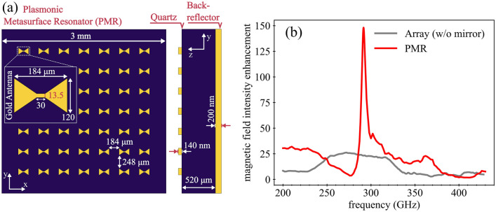
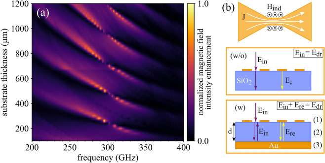
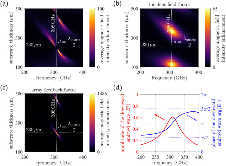
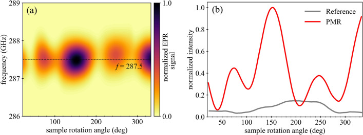
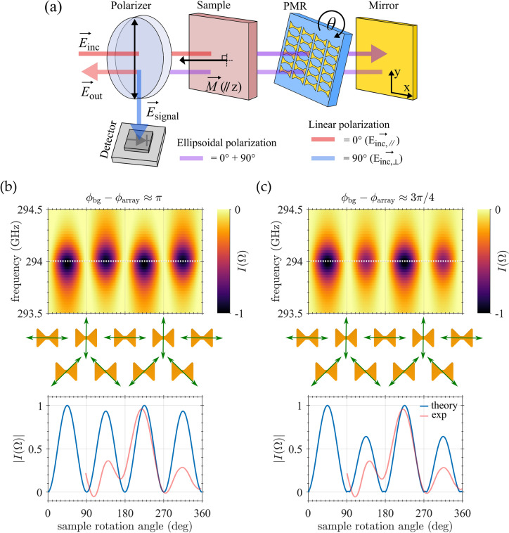
The increasing miniaturization of everyday devices necessitates advancements in surface-sensitive techniques to access phenomena more effectively. Magnetic resonance methods, such as nuclear or electron paramagnetic resonance, play a crucial role due to their unique analytical capabilities. Recently, the development of a novel plasmonic metasurface resonator aimed at boosting the THz electron magnetic response in 2D materials resulted in a significant magnetic field enhancement, confirmed by both numerical simulations and experimental data. Yet, the mechanisms driving this resonance were not explored in detail. In this study, we elucidate these mechanisms using two semi-analytical models: one addressing the resonant behaviour and the other examining the orientation-dependent response, considering the anisotropy of the antennas and experimental framework. Our findings contribute to advancing magnetic spectroscopic techniques, broadening their applicability to 2D systems.
Keywords: Cavity-enhanced; Electron paramagnetic resonance; Fabry-Pérot; Magnetic metasurface; Terahertz.
© 2024. The Author(s).
Conflict of interest statement
The authors declare no competing interests.
Figures
Similar articles
-
Plasmonic Metasurface Resonators to Enhance Terahertz Magnetic Fields for High-Frequency Electron Paramagnetic Resonance.Small Methods. 2021 Sep;5(9):e2100376. doi: 10.1002/smtd.202100376. Epub 2021 Jul 29. Small Methods. 2021. PMID: 34928064
-
THz Metamaterial Sensitivity Enhancement by Reduction of Substrate's Fabry-Pérot Oscillations Using Back Plates as an Optical De-Coupler.ACS Appl Mater Interfaces. 2024 Aug 28;16(34):45107-45118. doi: 10.1021/acsami.4c06187. Epub 2024 Aug 14. ACS Appl Mater Interfaces. 2024. PMID: 39143036
-
Terahertz binary computing in a coupled toroidal metasurface.Sci Rep. 2024 Apr 15;14(1):8721. doi: 10.1038/s41598-024-59069-5. Sci Rep. 2024. PMID: 38622184 Free PMC article.
-
Metasurface-Assisted Terahertz Sensing.Sensors (Basel). 2023 Jun 25;23(13):5902. doi: 10.3390/s23135902. Sensors (Basel). 2023. PMID: 37447747 Free PMC article. Review.
-
Cavity- and waveguide-resonators in electron paramagnetic resonance, nuclear magnetic resonance, and magnetic resonance imaging.Prog Nucl Magn Reson Spectrosc. 2014 Nov;83:1-20. doi: 10.1016/j.pnmrs.2014.09.003. Epub 2014 Oct 23. Prog Nucl Magn Reson Spectrosc. 2014. PMID: 25456314 Review.
References
-
- Ghosh A, et al. Evidence of compensated semimetal with electronic correlations at charge neutrality of twisted double bilayer graphene. Commun. Phys. 2023;6:360. doi: 10.1038/s42005-023-01480-x. - DOI
-
- Nakazawa K, Kato Y, Motome Y. Magnetic, transport and topological properties of Co-based shandite thin films. Commun. Phys. 2024;7:48. doi: 10.1038/s42005-024-01534-8. - DOI
-
- Kern M, et al. Hybrid spintronic materials from conducting polymers with molecular quantum bits. Adv. Funct. Mater. 2021;31:2006882. doi: 10.1002/adfm.202006882. - DOI
Grants and funding
LinkOut - more resources
Full Text Sources
