. 2024 Jul 8;16(1):238.
doi: 10.1007/s40820-024-01456-8.

Highly Efficient Back-End-of-Line Compatible Flexible Si-Based Optical Memristive Crossbar Array for Edge Neuromorphic Physiological Signal Processing and Bionic Machine Vision

Affiliations

Highly Efficient Back-End-of-Line Compatible Flexible Si-Based Optical Memristive Crossbar Array for Edge Neuromorphic Physiological Signal Processing and Bionic Machine Vision

Dayanand Kumar et al. Nanomicro Lett. .

Erratum in

Abstract

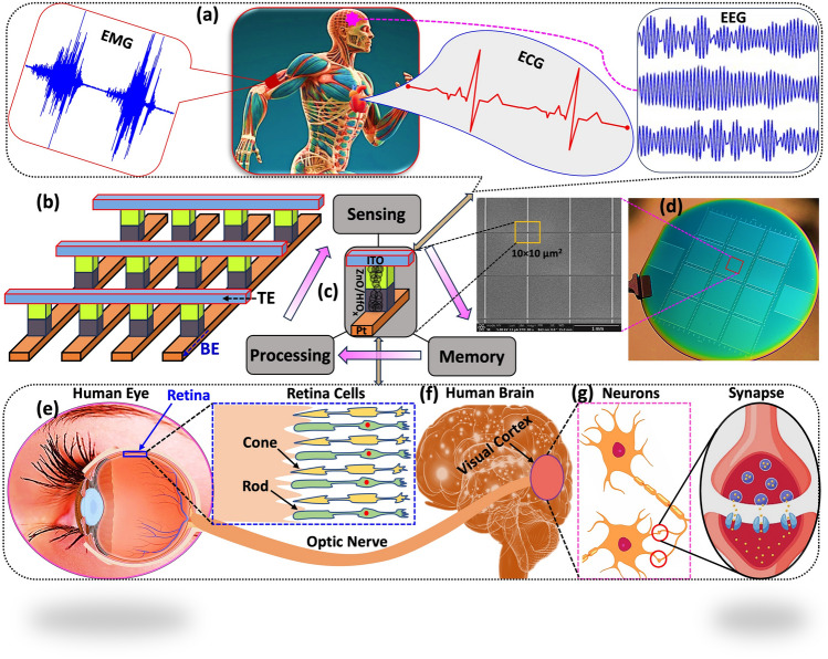
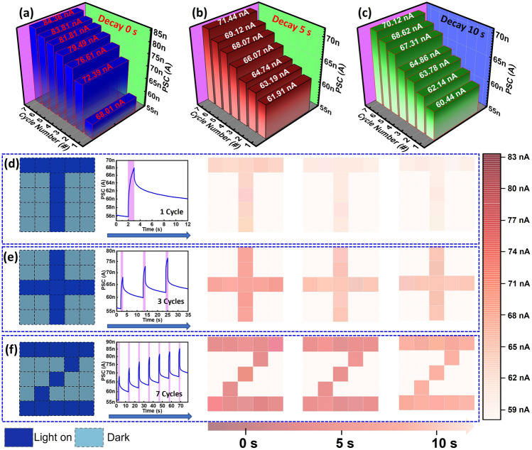
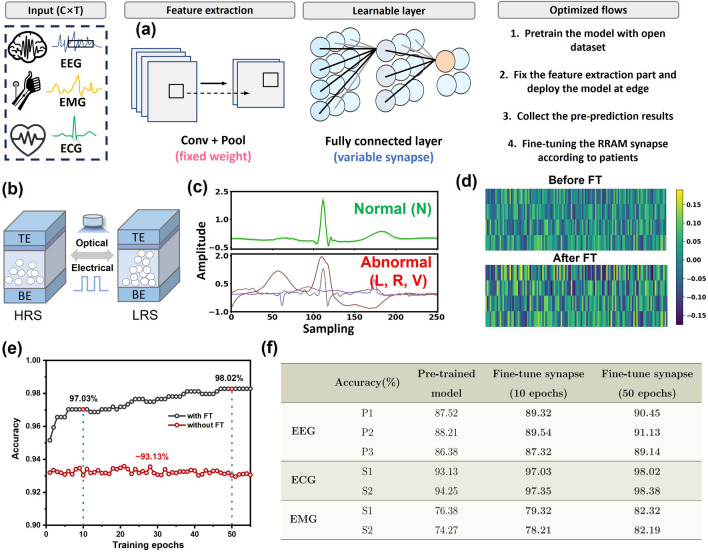
The emergence of the Internet-of-Things is anticipated to create a vast market for what are known as smart edge devices, opening numerous opportunities across countless domains, including personalized healthcare and advanced robotics. Leveraging 3D integration, edge devices can achieve unprecedented miniaturization while simultaneously boosting processing power and minimizing energy consumption. Here, we demonstrate a back-end-of-line compatible optoelectronic synapse with a transfer learning method on health care applications, including electroencephalogram (EEG)-based seizure prediction, electromyography (EMG)-based gesture recognition, and electrocardiogram (ECG)-based arrhythmia detection. With experiments on three biomedical datasets, we observe the classification accuracy improvement for the pretrained model with 2.93% on EEG, 4.90% on ECG, and 7.92% on EMG, respectively. The optical programming property of the device enables an ultra-low power (2.8 × 10⁻¹³ J) fine-tuning process and offers solutions for patient-specific issues in edge computing scenarios. Moreover, the device exhibits impressive light-sensitive characteristics that enable a range of light-triggered synaptic functions, making it promising for neuromorphic vision application. To display the benefits of these intricate synaptic properties, a 5 × 5 optoelectronic synapse array is developed, effectively simulating human visual perception and memory functions. The proposed flexible optoelectronic synapse holds immense potential for advancing the fields of neuromorphic physiological signal processing and artificial visual systems in wearable applications.

Keywords: Artificial vision system; Electrophysiological signal; Image recognition; Memristor; Neuromorphic computing.


Conflict of interest statement

The authors declare no interest conflict. They have no known competing financial interests or personal relationships that could have appeared to influence the work reported in this paper.

Figures

Fig. 1
Fig. 1
a Schematic diagram of physiological signals processing framework which is showing physiological organs such as EEG, EMG, and ECG of human body: Non-invasive EEG signals enable the reconstruction of consciousness patterns in the brain and the detection of eye movements for identity verification, EMG evaluates muscle and nerve function, assisting in diagnosing neuromuscular disorders and muscle-related issues, while ECG records the electrical activity of the heart, aiding in the diagnosis and monitoring of heart conditions like arrhythmias and heart attacks. b Schematic architecture of the crossbar array. c Integration of visible information sensing-memory-processing of the device. d Optical photographic image of the crossbar architecture which was fabricated on 4-inch Si wafer (there are 14 blocks on the wafer, and every block has 100 × 100 crossbar devices) and zoom in SEM image of the crossbar array with the cell size of 10×10 µm2. Schematic representation of the biological human visual system which is comprises the retina, optic nerve, and brain. e Detailed depiction of the human eye’s retina. f Diagram of the human brain. g Schematic illustration of neurotransmitter between pre-synaptic and post-synaptic sites in the retina
Fig. 2
Fig. 2
a, b HR-TEM cross-sectional images of the ITO/ZnO/HfOx/Pt device, with scale bars of 200 nm and 20 nm, respectively. c, d Color TEM and EDS line profiles are used to confirm the presence of various elements within the device. e-j EDS elemental mapping for Pt, Hf, Zn, O, Sn, and In within the device. kn Depth scan XPS spectra of Hf 4f, Zn 2p, and O 1s peaks in HfOx and ZnO layers
Fig. 3
Fig. 3
Electrical and synaptic properties of the ITO/ZnO/HfOx/Pt device. a Schematic representation of the device. b Electrical I–V characteristics of the memristor, showcasing positive SET (0.7 V) and negative RESET (-0.5 V) transitions. c AC endurance of the memristive device at a speed of 100 μs for both SET and RESET operations. d Short-term potentiation (STP) to long-term potentiation (LTP) and short-term depression (STD) to long-term depression (LTD) of the memristor, induced by a series of voltage pulses (+ 0.8 V for potentiation, -1 V for depression, pulse width: 100, 300, and 500 ns). e Repetitive potentiation and depression 1728 cycles. f Paired-pulse facilitation (PPF) index of the device. Inset: schematic depiction of the paired-pulse facilitation measurement
Fig. 4
Fig. 4
a Schematic representation of biological synapse and artificial optoelectronic memristive synapse. b Light-induced photonic potentiation using a single blue light (wavelength: 456 nm, light intensity: 9.5 mW cm−2, duration: 5 s, indicated by the purple-colored area), and electrical erasure using a voltage pulse (amplitude: − 1 V, duration: 100 µs) in the optical memristive device. c Photocurrent response under light for 3 s (indicated by the coral-colored area) at various light intensities (dark, 2.7, 3.6, 5.2, 6.9, and 9.5 mW cm−2), followed by photocurrent decay when the light is turned off. d Photocurrent response under a light intensity of 9.5 mW cm−2 with different time durations (1, 2, 3, 4, and 5 s), followed by photocurrent decay when the light is turned off. e PSC of the device for PPF index variation with the time interval (Δt) of photonic pulse pairs. Inset: PSC under blue light (intensity: 9.5 mW cm−2, duration: 1 s) pulse pairs with a 10 s time interval. f Photocurrent response under consecutive light pulses. Inset: zoom view of. g Learning-forgetting-relearning process over seven cycles
Fig. 5
Fig. 5
Fig. 5 a Photograph of fabricated arrays, b photograph of the flexible photonic memristive synapse during optical measurements, and c photograph of the flexing of the device. d RS characteristics though I-V sweep under flat and bent conditions (2 cm). e Endurance characteristics under mended conditions measured up to 100 cycles. f Device variability of the fabricated devices under bending conditions in on and off states of the devices. g PSC of the device using a single blue light during flat and bending conditions (wavelength: 456 nm, light intensity: 9.5 mW cm−2, duration: 5 s, indicated by the purple-colored area). h Photocurrent response under light for 3 s (indicated by the green-colored area) at various light intensities (2.7, 3.6, 5.2, 6.9, and 9.5 mW cm−2), followed by photocurrent decay when the light is turned off. i PSC under a light intensity of 9.5 mW cm−2 with different time durations (1, 2, 3, 4, and 5 s), followed by photocurrent decay when the light is turned off. j Photocurrent response under consecutive light pulses. k The zoom view of j. l Learning-forgetting-relearning process over seven cycles. m PPF index variation with the time interval (Δt) of photonic pulse pairs. Inset: PSC under blue light (intensity: 9.5 mW cm−2, duration: 1 s) pulse pairs with a 10 s time interval.
Fig. 6
Fig. 6
The current conductance of the optoelectronic memristor after various number of cycles at a 0 s, b 10 s, and c 5 s decay time. The image mapping for current conductance after d 1 cycle, e 3 cycles, and f 7 cycles
Fig. 7
Fig. 7
a Concept of edge biomedical AI processor. b Conductance state change on ITO/ZnO/HfOx/Pt crossbar array. c ECG signal visualization for normal and abnormal events. d Weight map visualization before and after fine-tune process. e Training accuracy behaves with and without fine-tune process for ECG based arrhythmia detection. f Comparison table of training accuracy for three bio-signals

References

    1. F. Zhou, Y. Chai, Near-sensor and in-sensor computing. Nat. Electron. 3, 664–671 (2020). 10.1038/s41928-020-00501-9
    1. V.M. Ho, J.A. Lee, K.C. Martin, The cell biology of synaptic plasticity. Science 333, 623 (2011). 10.1126/science.1209168 - PMC - PubMed
    1. K. Liang, R. Wang, B. Huo, H. Ren, D. Li et al., Fully printed optoelectronic synaptic transistors based on quantum dot-metal oxide semiconductor heterojunctions. ACS Nano 16, 8651–8661 (2022). 10.1021/acsnano.2c00439 - PubMed
    1. N. Ilyas, J. Wang, C. Li, D. Li, H. Fu et al., Nanostructured materials and architectures for advanced optoelectronic synaptic devices. Adv. Funct. Mater. 32, 2110976 (2022). 10.1002/adfm.202110976
    1. X. Han, Z. Xu, W. Wu, X. Liu, P. Yan et al., Recent progress in optoelectronic synapses for artificial visual-perception system. Small Struct. 1, 2000029 (2020). 10.1002/sstr.202000029

LinkOut - more resources