. 2024 Sep 26;69(10):1245-1254.
doi: 10.4187/respcare.11696.

Development of a New Method for Evaluating Heat and Moisture Exchanger Performance

Affiliations

Development of a New Method for Evaluating Heat and Moisture Exchanger Performance

Kouhei Nagata et al. Respir Care. .

Abstract

Background: A model system described in International Organization for Standardization 9360 is the standard method for estimating the humidifying performance of heat and moisture exchangers (HMEs). However, there are no reliable bedside methods for evaluating the ongoing humidification performance of HMEs. Therefore, this study aimed to develop 2 clinically applicable methods for estimating the ongoing humidifying performance of HMEs and to evaluate their reliability in a model system.

Methods: Physiologically expired gas was simulated using a heated humidifier, and ventilation was delivered using a ventilator with constant flow through 3 different types of HMEs. Relative humidity (RH) was measured using a capacitive-type moisture sensor. Water content lost during expiration was calculated by integrating absolute humidity (AH), instantaneous gas flow measured at the expiratory outlet of the ventilator, and time. We also calculated the water content released and captured by the HMEs during tidal ventilation by integrating the difference in AH across the HMEs, instantaneous gas flow, and time.

Results: We found that the RH, temperature, and AH were almost constant on the expiratory outlet of the ventilator but rapidly varied near the HMEs. The water content lost by the 3 HMEs was associated with the manufacturer-reported values and inversely correlated with the calculated values of the water content exchanged by the HMEs. The water content released and captured by HMEs was closely correlated with the difference in HME weight measured at the end of inspiration and expiration; however, the water content captured by HMEs seemed to be overestimated.

Conclusions: Our results demonstrated that our system was able to detect the differences in the performance of 3 models of HMEs and suggest that our method for calculating water loss is reliable for estimating the water retention performance of HMEs during mechanical ventilation, even in the presence of a constant flow.

Keywords: Heat and moisture exchanger; humidification; humidity; mechanical ventilation; water content; water exchange; water retention.


Conflict of interest statement

The authors have disclosed no conflicts of interest.

Figures

Fig. 1.
Fig. 1.
The model system used in this study. The side of the heat and moisture exchanger connected to the MR850 and the model lung was indicated as the patient side, whereas the other side connected to the Servo-air was indicated as the ventilator side. A mixing box with a fan inside was attached to the expiratory outlet of the ventilator (expiratory side). The patient side of the model comprised a test lung, a heated humidifier, respiratory hoses with heating wires in them, 2 one-way valves, a simulated tracheal tube, and a Y-piece. The patient side simulates a patient’s lungs to exhale physiologically humid gas. The ventilator side comprises a ventilator, respiratory hoses, and a Y-piece. The expiratory side had a mixing chamber connected to the expiratory outlet of the Servo-air. Each pair of moisture sensors and thermistors was located at the patient, ventilator, and expiratory sides. On the ventilator and expiratory sides, the flow meters were positioned next to the respective sensors. Fan = mixing box with a fan inside; HME = heat and moisture exchanger; HH = heated humidifier.
Fig. 2.
Fig. 2.
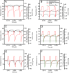
Representative recordings of relative humidity (RH), temperature, and gas flow measured using Inter-Therm (A, B, C) and Inter-Therm Mini (D, E, F) after 60 min of test ventilation. A, D: RH and temperature were measured on the patient’s (P) side. B, E: RH and temperature were measured on the ventilator (V) side. C, F: RH and temperature were measured on the expiratory outlet of the ventilator. Gas flow was measured on both the V and Ex side. The gas flow measured on the expiratory outlet of the ventilator was > that measured on the ventilator side during the late part of the expiratory phase because of the presence of the constant flow. Compared with RH measured using Inter-Therm, that measured using Inter-Therm Mini was lower during the late part of inspiration on the patient side and higher during expiration on the V and Ex sides. Temperature P, V, and X: temperature measured on the P, V, and Ex sides. RH P, V, and X: RH measured on the P, V, and Ex sides. Flow: gas flow measured on the ventilator side. Flow Ex: gas flow measured on the expiratory outlet of the ventilator.
Fig. 3.
Fig. 3.
Representative recordings of calculated changes in absolute humidity (AH) and gas flow measured using Inter-Therm (A) and Inter-Therm Mini (C), both corresponding to Figure 1. Representative recordings of calculated changes in the water content in heat and moisture exchangers (HMEs) and water content lost by HMEs during expiration were measured using Inter-Therm (B) and Inter-Therm Mini (D), corresponding to Figures 2A and C. Compared with the Inter-Therm recordings, the Inter-Therm Mini recordings showed lower AH on the patient’s side (AHP) during inspiration and higher AH on the ventilator side (AHV) during expiration (A, C). Compared with the Inter-Therm recordings, the Inter-Therm Mini recordings showed smaller respiratory changes in water HME and larger amplitudes of water Ex (B, D). AHP, AHV, and AH at the expiratory outlet of the ventilator: AH measured on the P, V, and Ex sides. Water Ex: calculated water content lost by the HME during expiration. Water HME: calculated changes in the water content of HMEs. Flow = gas flow measured on the ventilator side. AHV = absolute humidity on the ventilator side; AHP = absolute humidity on the patient’s side; AHEx = absolute humidity at the expiratory outlet of the ventilator; AH = absolute humidity; HME = heat and moisture exchanger.
Fig. 4.
Fig. 4.
Representative recordings of gas flow, respiratory circuit pressure, and water content in heat and moisture exchangers (HMEs) (A). Measurements of changes in HME weight and comparison of these changes with water R and C (B, C, D). Pressing the pause button during inspiration stops gas flow at the end of inspiration and keeps the water content in HMEs constant at the level of end inspiration during the I pause (A). Respiratory circuit pressure measured on the patient side decreased slightly during the I pause, probably because of the small leak in the circuit. The same maneuver during expiration causes the same effect on gas flow and keeps the water content in HMEs constant at the level of end expiration during the E pause. The HME weight was measured 4 times at the end of inspiration and expiration for each condition. B: Measurements were made using Inter-Therm at tidal volumes of 500 mL and 1,000 mL. C: Comparison between water R and HME weight changes. D: Comparison between water C and HME weight changes. The Spearman rank correlation coefficient was 0.923 between the HME weight and water R, whereas it was 0.909 between the HME weight and water C. The red lines represent the linear regression lines, which are as follows: y = 0.828x + 4.87, r = 0.963 for y = water R, x = HME weight; and y = 1.016x + 3.62, r = 0.962 for y = water C, x = HME weight. Water R: calculated water content released by HMEs during tidal inspiration; water C: calculated water content captured by HMEs during tidal expiration; I pause: end-inspiratory pause is induced by pressing the pause button during inspiration; E pause: end-expiratory pause is induced by pressing the pause button during expiration. HME = heat and moisture exchanger; VT = tidal volume.

Comment in

References

    1. Gillies D, Todd DA, Foster JP, Batuwitage BT. Heat and moisture exchangers versus heated humidifiers for mechanically ventilated adults and children. Cochrane Database Syst Rev 2017;9(9):CD004711. - PMC - PubMed
    1. Vargas M, Chiumello D, Sutherasan Y, Ball L, Esquinas AM, Pelosi P, et al. Heat and moisture exchangers (HMEs) and heated humidifiers (HHs) in adult critically ill patients: a systematic review, meta-analysis, and meta-regression of randomized controlled trials. Crit Care 2017;21(1):123. - PMC - PubMed
    1. Restrepo RD, Walsh BK; American Association for Respiratory Care. Humidification during invasive and noninvasive mechanical ventilation: 2012. Respir Care 2012;57(5):782-788. - PubMed
    1. Djedaini K, Billiard M, Mier L, Le Bourdelles G, Brun P, Markowicz P, et al. Changing heat and moisture exchangers every 48 hours rather than 24 hours does not affect their efficacy and the incidence of nosocomial pneumonia. Am J Respir Crit Care Med 1995;152(5 Pt 1):1562-1569. - PubMed
    1. Lellouche F, Taille S, Lefrancois F, Deye N, Maggiore SM, Jouvet P, et al. ; Groupe de travail sur les Respirateurs de l’AP-HP. Humidification performance of 48 passive airway humidifiers: comparison with manufacturer data. Chest 2009;135(2):276-286. - PubMed

Publication types

LinkOut - more resources