Review
. 2024 Jul 2;17(13):3273.
doi: 10.3390/ma17133273.

Abrasive Waterjet Machining

Affiliations
Review

Abrasive Waterjet Machining

Mohamed Hashish. Materials (Basel). .

Abstract

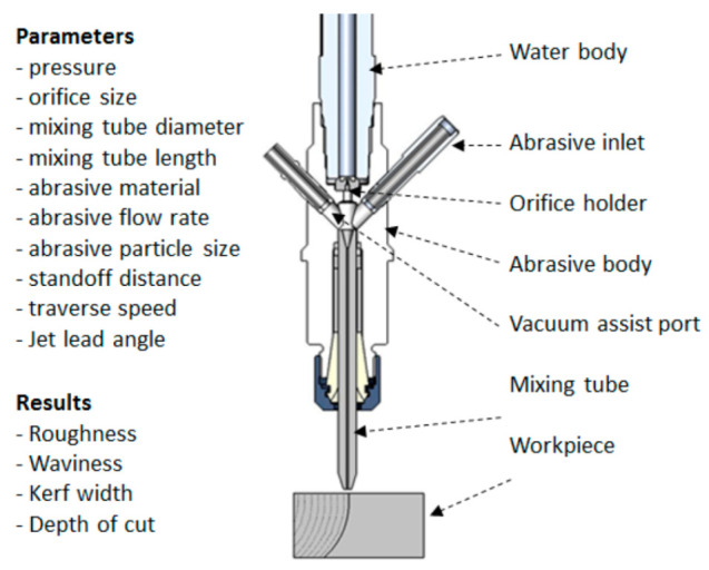
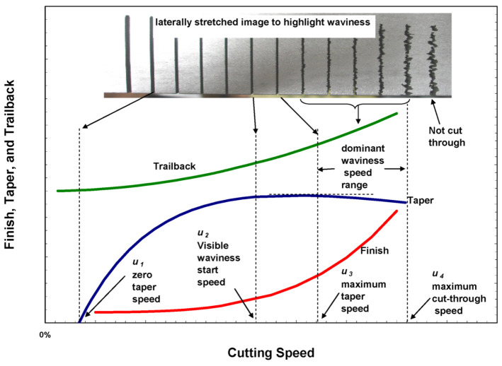
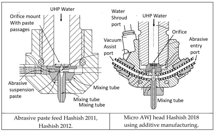
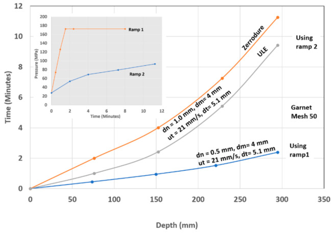
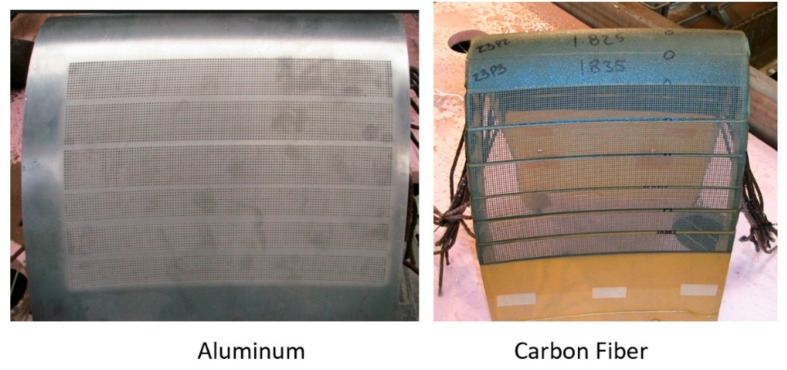
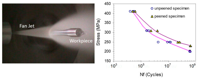
The abrasive waterjet machining process was introduced in the 1980s as a new cutting tool; the process has the ability to cut almost any material. Currently, the AWJ process is used in many world-class factories, producing parts for use in daily life. A description of this process and its influencing parameters are first presented in this paper, along with process models for the AWJ tool itself and also for the jet-material interaction. The AWJ material removal process occurs through the high-velocity impact of abrasive particles, whose tips micromachine the material at the microscopic scale, with no thermal or mechanical adverse effects. The macro-characteristics of the cut surface, such as its taper, trailback, and waviness, are discussed, along with methods of improving the geometrical accuracy of the cut parts using these attributes. For example, dynamic angular compensation is used to correct for the taper and undercut in shape cutting. The surface finish is controlled by the cutting speed, hydraulic, and abrasive parameters using software and process models built into the controllers of CNC machines. In addition to shape cutting, edge trimming is presented, with a focus on the carbon fiber composites used in aircraft and automotive structures, where special AWJ tools and manipulators are used. Examples of the precision cutting of microelectronic and solar cell parts are discussed to describe the special techniques that are used, such as machine vision and vacuum-assist, which have been found to be essential to the integrity and accuracy of cut parts. The use of the AWJ machining process was extended to other applications, such as drilling, boring, milling, turning, and surface modification, which are presented in this paper as actual industrial applications. To demonstrate the versatility of the AWJ machining process, the data in this paper were selected to cover a wide range of materials, such as metal, glass, composites, and ceramics, and also a wide range of thicknesses, from 1 mm to 600 mm. The trends of Industry 4.0 and 5.0, AI, and IoT are also presented.

Keywords: abrasive waterjet; composites; cutting; drilling; glass; metal; milling; surface finish; titanium; trimming; waterjet.


Conflict of interest statement

Author Mohamed Hashish was employed by the company Flow International Corporation. The author declares that the research was conducted in the absence of any commercial or financial relationships that could be construed as a potential conflict of interest.

Figures

Figure 1
Figure 1
Waterjet system components.
Figure 2
Figure 2
AWJ parameters.
Figure 3
Figure 3
Waterjet orifices.
Figure 4
Figure 4
Waterjets with different upstream conditions at 350 MPa pressure.
Figure 5
Figure 5
Waterjet flow, power, and orifice size relationships.
Figure 6
Figure 6
Abrasive particle shape indices and preferred zone (upper left corner).
Figure 7
Figure 7
AWJ nozzle and suction hose characteristics [24].
Figure 8
Figure 8
Example of mixing tube wear.
Figure 9
Figure 9
Geometrical attributes of waterjet cutting.
Figure 10
Figure 10
Erosion model.
Figure 11
Figure 11
AWJ cutting model showing step and cutting stages.
Figure 12
Figure 12
Idealized model of surface waviness.
Figure 13
Figure 13
Effect of abrasive particle size on surface roughness.
Figure 14
Figure 14
Trailback geometry for several cuts in titanium.
Figure 15
Figure 15
Universal kerf shape and data from Figure 14.
Figure 16
Figure 16
Theoretical waterjet kerf profiles.
Figure 17
Figure 17
Kerf width profile in 150 mm thick titanium.
Figure 18
Figure 18
AWJ cuts showing kerf top, bottom, side, and surface morphology.
Figure 19
Figure 19
Cutting speed zones.
Figure 20
Figure 20
Gain in speed due to dynamic jet tilting.
Figure 21
Figure 21
Undercutting at the bottom of cuts.
Figure 22
Figure 22
Examples of AWJ applications in jet engines.
Figure 23
Figure 23
Composite use in aircraft.
Figure 24
Figure 24
CFRP parts on the Airbus 350.
Figure 25
Figure 25
Examples of cutting microelectronic parts.
Figure 26
Figure 26
Examples of AWJ glass cutting and milling.
Figure 27
Figure 27
AWJ stone cutting and inlay.
Figure 28
Figure 28
Examples of automotive applications.
Figure 29
Figure 29
Example of thin sheet metal cutting data.
Figure 30
Figure 30
AWJ end effector with height sensor and vision camera.
Figure 31
Figure 31
Sample holes for vent screens.
Figure 32
Figure 32
Titanium screen cutting.
Figure 33
Figure 33
Precision robotic cutting of glass domes for solar panels.
Figure 34
Figure 34
Microblaster abrasive feed for fine abrasives.
Figure 35
Figure 35
MicroSD singulation using AWJ technology.
Figure 36
Figure 36
EHC before and after AWJ cutting.
Figure 37
Figure 37
Trailback curve rotation with lead angles in glass.
Figure 38
Figure 38
Kerf width profile rotation in 100 mm thick titanium.
Figure 39
Figure 39
Example data on kerf width and trailback.
Figure 40
Figure 40
Thick glass cutting of small demo parts. The arrows show the cutting path.
Figure 41
Figure 41
Cutting 600 mm thick glass using a 900 mm long mixing tube. The arrows show the cutting path starting from the center.
Figure 42
Figure 42
Maximum cutting speeds and trailbacks in titanium.
Figure 43
Figure 43
Surface waviness as a function of cutting speed.
Figure 44
Figure 44
Near-net shaping of integrated jet engine rotor blades.
Figure 45
Figure 45
Potential integrity problems faced when using solid tools.
Figure 46
Figure 46
Stringer trimming for the Boeing 787 aircraft.
Figure 47
Figure 47
Stringer trimming machine for the Boeing 787 wing stringers.
Figure 48
Figure 48
AWJ composite machining systems.
Figure 49
Figure 49
Focal point C-frame end effector for composite trimming.
Figure 50
Figure 50
Sample AWJ-cut taper and finish.
Figure 51
Figure 51
Examples of small composite parts.
Figure 52
Figure 52
Robotic trimming of small composite clips.
Figure 53
Figure 53
Geometry of fan blades and a blade trimming test.
Figure 54
Figure 54
A varying thickness portion of an AWJ-trimmed fan blade.
Figure 55
Figure 55
Cuts made in sapphire and SiC/SiC composite material.
Figure 56
Figure 56
Effect of the cutting speed on the taper of the cut in SiC/SiC material.
Figure 57
Figure 57
Micro AWJ with a 177-micron mixing tube [78].
Figure 58
Figure 58
Cutting results with a micro AWJ tool.
Figure 59
Figure 59
Patented micro AWJ cutting heads [81,82,83].
Figure 60
Figure 60
Micro AWJ sizes from the literatures [60,78,80,85,86].
Figure 61
Figure 61
Micro AWJ cutting head, Craigen and Hashish [81].
Figure 62
Figure 62
Example features machined with micro AWJ technology.
Figure 63
Figure 63
Micro sidefire AWJ cutting head for groove milling.
Figure 64
Figure 64
Hole piercing progression examples.
Figure 65
Figure 65
Possible hole shapes with AWJ piercing.
Figure 66
Figure 66
Cross-sections of holes drilled in aluminum and steel (dn = 0.18 mm, dm = 0.51 mm, P = 345 MPa).
Figure 67
Figure 67
Drilling times for steel and aluminum at different depths.
Figure 68
Figure 68
Effect of pressure on the drilling time for 12.7 mm thick steel and aluminum.
Figure 69
Figure 69
Small-diameter holes drilled in a 20 mm thick steel block.
Figure 70
Figure 70
Hole depth progression in steel at different eccentricities.
Figure 71
Figure 71
Holes drilled in glass.
Figure 72
Figure 72
Drilling rate in thick glass under different conditions.
Figure 73
Figure 73
Repeatability of hole drilling in thick glass.
Figure 74
Figure 74
Possible problems of drilling a TBC using AWJ technology.
Figure 75
Figure 75
Accurately drilled hole at 30 degrees.
Figure 76
Figure 76
AWJ-drilled holes in TBC.
Figure 77
Figure 77
AWJ-drilled hole in an alumina/alumina CMC with no adverse effects.
Figure 78
Figure 78
AWJ-drilled shaped hole in SiC/SiC material.
Figure 79
Figure 79
Hole circularity measurement in an alumina CMC.
Figure 80
Figure 80
Potential failure modes in AWJ drilling.
Figure 81
Figure 81
AWJ piercing through a 25 mm thick composite at a shallow angle.
Figure 82
Figure 82
Cutting head for precision cutting and drilling.
Figure 83
Figure 83
Matching holes drilled in aluminum and carbon fiber composite.
Figure 84
Figure 84
Closely packed AWJ-drilled holes in 1 mm thick CFRP.
Figure 85
Figure 85
Example of pierced shaped holes.
Figure 86
Figure 86
Hole boring pilot and reaming AWJ tools.
Figure 87
Figure 87
AWJ-bored holes.
Figure 88
Figure 88
Milling methods using masks.
Figure 89
Figure 89
Isogrid milling (radial and cylindrical).
Figure 90
Figure 90
Milling of jet engine exhaust heat shield tiles.
Figure 91
Figure 91
Milling of telescope face sheet glass.
Figure 92
Figure 92
Deep pocket milling examples.
Figure 93
Figure 93
Typical composite joint designs.
Figure 94
Figure 94
AWJ-milled composite repair joints.
Figure 95
Figure 95
AWJ grooving examples.
Figure 96
Figure 96
Turning operations.
Figure 97
Figure 97
Example samples of turning operations.
Figure 98
Figure 98
Example turning trends using Ti-Al target material.
Figure 99
Figure 99
Turning process parameters used for modeling.
Figure 100
Figure 100
Segmental turning.
Figure 101
Figure 101
Example of early multi-operation machining.
Figure 102
Figure 102
Shaping of titanium aluminide blades.
Figure 103
Figure 103
AWJ cuts for a 3D laminated object.
Figure 104
Figure 104
Stent polishing.
Figure 105
Figure 105
Waterjet texturing of automotive cylinder bore.
Figure 106
Figure 106
Effect of waterjet impact of fatigue parameters for 7075-T6 aluminum.
Figure 107
Figure 107
Examples of pure waterjet cutting at elevated pressures.
Figure 108
Figure 108
Effect of pressure on non-delamination cutting speed.
Figure 109
Figure 109
Mechanical–waterjet hybrid composite machining system.
Figure 110
Figure 110
AWJ-EDM hybrid machine.
Figure 111
Figure 111
Effect of upstream cooling on nitrogen jet structures.
Figure 112
Figure 112
Steel plate cut with a liquid nitrogen ACJ.

References

    1. Hashish M. Steel Cutting with Abrasive-Waterjets; Proceedings of the 6th International Symposium on Jet Cutting Technology, BHRA; Guildford, UK. 6–8 April 1982; pp. 465–487.
    1. Hashish M. Cutting with Abrasive-Waterjets. Mech. Eng. 1984;106:60–66.
    1. Hashish M. Waterjet Cutting Studies; Proceedings of the 16th International Water Jetting Technology Conference, BHR Group; Aix-en-Provence, France. 16–18 October 2002; pp. 13–48.
    1. Hashish M. The Waterjet as a Tool; Proceedings of the 14th International Water Jet Cutting Technology Conference, BHR Group; Brugge, Belgium. 12–14 October 1998.
    1. Varun R., Nanjundeswaraswamy T.S. A Literature Review on Parameters Influencing Abrasive Jet Machining and Abrasive Water Jet Machining. Eng. Res. Appl. 2019;9:24–29.

LinkOut - more resources