Review
. 2024 Jul 3;14(7):789.
doi: 10.3390/biom14070789.

Alginate-Based Electrospun Nanofibers and the Enabled Drug Controlled Release Profiles: A Review

Affiliations
Review

Alginate-Based Electrospun Nanofibers and the Enabled Drug Controlled Release Profiles: A Review

Zhiyuan Zhang et al. Biomolecules. .

Abstract

Alginate is a natural polymer with good biocompatible properties and is a potential polymeric material for the sustainable development and replacement of petroleum derivatives. However, the non-spinnability of pure alginate solutions has hindered the expansion of alginate applications. With the continuous development of electrospinning technology, synthetic polymers, such as PEO and PVA, are used as co-spinning agents to increase the spinnability of alginate. Moreover, the coaxial, parallel Janus, tertiary and other diverse and novel electrospun fiber structures prepared by multi-fluid electrospinning have found a new breakthrough for the problem of poor spinning of natural polymers. Meanwhile, the diverse electrospun fiber structures effectively achieve multiple release modes of drugs. The powerful combination of alginate and electrostatic spinning is widely used in many biomedical fields, such as tissue engineering, regenerative engineering, bioscaffolds, and drug delivery, and the research fever continues to climb. This is particularly true for the controlled delivery aspect of drugs. This review provides a brief overview of alginate, introduces new advances in electrostatic spinning, and highlights the research progress of alginate-based electrospun nanofibers in achieving various controlled release modes, such as pulsed release, sustained release, biphasic release, responsive release, and targeted release.

Keywords: alginate; biomedical; controlled release; drug delivery; electrospinning; nanostructure.


Conflict of interest statement

The authors declare no conflicts of interest.

Figures
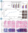
Figure 10
Figure 10
(A) (a) Release profile of AF protein from composite electrospun fiber dressing. (b) MTT assay of different composite dressings during 5-day incubation (** p < 0.01, *** p < 0.001) [115]. (B) (a) The quantification results of released silver from PCL30/A in PBS at 37 °C. (b,c) In vivo study of wound healing using composite fibers. (b) The healing of wounds covered by different dressings. Red dashed circles indicate the size of the wound created. (c) The quantification results of the wound closure (* p < 0.05. ** p < 0.01 compared to the control group) [20]. (C) Histologic analysis of bone repair: H&E staining and MTC staining at 4 and 8 weeks after implantation. White circles: osteoblasts; white arrows: Haver’s canal; HB, NB, and MB are host, new, and mature bone, respectively; MC is bone marrow cavity; L is lamellar; and V is vascular. The black scale bar is 200 μm, and the green scale bar is 50 μm [135].
Figure 1
Figure 1
Statistics of literature retrieval on the “Web of Science” platform with the subjects of “Alginate & Electrospinning” and “Alginate & Electrospinning & drug delivery”.
Figure 2
Figure 2
Alginate electrospun fibers for biomedical applications and for drug delivery and controlled release modalities.
Figure 3
Figure 3
(A) Structures of alginate epimeric blocks: (a) β-d-mannuronic acid (M block) and (b) α-l-guluronic acid (G block) as well as homopolymer blocks; (c) MM block (mannuronic acid) and (d) GG block (guluronic acid). (B) Schematic diagram of CaCl2 cross-linked SA.
Figure 4
Figure 4
(A) TEM image of embedded nanosilver PCL fibers. (scale = 100 nm) [20]. (B) SEM images of 0.2% (w/v) collagen grafted nanofiber [74]. (C) TEM image of HNT-LEV/SA-PEO nanocomposite fibers at an electron acceleration voltage of 100 kV (scale = 300 nm) [65]. (D) Schematic diagram of the research-designed electrospinning process (two-column diagram) [65].
Figure 5
Figure 5
(A) TEM images showing the coaxial structure of nanofibers [85]. (B) Schematic diagram of the electrospinning of Janus fibers through different spinnerets [29]. (C) (a) Digital photograph of a concentric side-by-side nozzle design. (b) TEM images of Janus-structured electrospun fibers simultaneously loaded with CIPs and AgNPs [87]. (D) Design diagram of the preparation of electrospun juxtaposed structured nanofibers [88].
Figure 6
Figure 6
(A) Design of an electrospun spinneret with a “pig snout” three-fluid homogeneous shell-separated double core: (a) front view; (b) side view; structural outlets from three inlets [101]. (B) (a) Preparation of chimeric Janus microfibers with a specially designed multi-fluid complex spinneret and detection of their wettability; (b) TEM images of chimeric Janus microfiber [30].
Figure 7
Figure 7
(AE) Schematic of five trends in drug release: (A) Pulse release; (B) Sustained release; (C) zero-order release; (D) biphasic release; (E) Response Release; (F) Effective therapeutic range of drugs, Minimum Effective Concentration (MEC), Maximum non-toxic concentration (MNC).
Figure 8
Figure 8
(A) Schematic of the electrodischarge nanofiber triple-layer wound dressing; (B) Release profiles of electrospun fiber-loaded doxycycline from coaxial electrospun fibers and three-layer wound dressing. A8:1.5% PCL + 4.5 % Collagen; A9:1% PCL + 4.5% Collagen; A9-W1: A9 coaxial nanofibers + SANFs + CS nanofibers; A8-W2: A8 coaxial nanofibers +  SANFs + CS nanofibers [116].
Figure 9
Figure 9
(A) Release rate of composite nanofibers loaded with different TCH contents [117]. (B) FE-SEM images. Transverse images of (a) drug-loaded nanoparticles, (b) PCL electrospun fibers, (c) composite fiber mats, and (d) multilayered composite scaffolds (electrospun mats are indicated by arrows) [118]. (C) (a) KGN calibration curves, (b) cumulative release profiles of KGN from particles, hydrogels, and composites over 30 days, (c) cumulative release profiles of KGN from particles, hydrogels, and composites over 24 h, and (d) images of the water contact angle of electrospun mats and hydrogels [118]. (D) (a) Raisinomycin assay of scaffolds with different culture times (Values represent the mean ± SD, n = 3, * p < 0.05, *** p < 0.001). (b) Live/dead cell viability assay after 1, 3, and 7 days on Alg:Alg-Sul hydrogels with or without KGN-NPs [118]. (E) (a) Schematic of the release mechanism of LEV from nanohybrids. (b) Drug release profiles from different fractions of fibers over 7 days [65]. (F) (ad) Sections of the infarct border zone on day 28 of culture were collected and immunofluorescently stained for the endothelial marker CD31 and α-smooth muscle actin (SMA) (*** p < 0.001; ns, nonsignificant). (a) Cardiomyocytes were stained with SMA, and nuclei were counterstained with DAPI. Scale bar: 75 μm. Border zone vessel density (b) was quantified as the expression of CD31; arteriolar density (c) was quantified as the number of vasculature-like structures expressing SMA (n = 4). (d) Images of micro-CT scans after imaging with Microfil. Scale bars: 2 mm and 500 µm [19].
Figure 11
Figure 11
(A) (a) Schematic diagram of the preparation of electrospun nanofibers with a core-shell structure, using SA as the shell layer and previously prepared CS nanoparticles loaded with BSA as the core layer. (b) Diffusion release coefficients of BSA in SGF, SIF, and SCF media [108]. (B) Simulation of BSA release from electrospun fibers during transport from the oral cavity to the colon [139].
Figure 12
Figure 12
(A) (a) Schematic diagram of curcumin-loaded sponge-electrospun fiber-sponge sandwich structure for rapid hemostasis dressing and the prevention of tumor recurrence after surgery. (b) Dimensions of recurrent solid tumors on postoperative day 16 in different post-treatment groups [12]. (B) Two strategies for treating wound models. RALA/miR nanoparticles (NPs) containing 5 µg of miR and ALG/PVA/CIP nanofibers (NFs) containing 2.5 µg of miR. (a) Creation of a full-thickness wound model and comparison of treatments. (b) Remaining wound area at postoperative days 2, 4, and 7 in different groups after wound treatment. Data are reported as mean ± SEM, n = 5, and statistical significance is calculated by means of two-way ANOVA (* p < 0.05, ** p < 0.01). (C) Promotion of wound healing using different post-treatments. C57BL/6N mice to construct a thick incision wound-healing model. Representative images of wound closure on days 2, 4, and 7 were recorded. n = 5 [143].

Similar articles

Cited by

References

    1. Pawar S.N., Edgar K.J. Alginate Derivatization: A Review of Chemistry, Properties and Applications. Biomaterials. 2012;33:3279–3305. doi: 10.1016/j.biomaterials.2012.01.007. - DOI - PubMed
    1. Priya S., Batra U., Samshritha R.S., Sharma S., Chaurasiya A., Singhvi G. Polysaccharide-Based Nanofibers for Pharmaceutical and Biomedical Applications: A Review. Int. J. Biol. Macromol. 2022;218:209–224. doi: 10.1016/j.ijbiomac.2022.07.118. - DOI - PubMed
    1. Hinderer S., Layland S.L., Schenke-Layland K. ECM and ECM-like Materials—Biomaterials for Applications in Regenerative Medicine and Cancer Therapy. Adv. Drug Deliv. Rev. 2016;97:260–269. doi: 10.1016/j.addr.2015.11.019. - DOI - PubMed
    1. Rezaei S., Valipouri A., Hosseini Ravandi S.A., Kouhi M., Ghasemi Mobarakeh L. Fabrication, Characterization, and Drug Release Study of Vitamin C–Loaded Alginate/Polyethylene Oxide Nanofibers for the Treatment of a Skin Disorder. Polym. Adv. Technol. 2019;30:2447–2457. doi: 10.1002/pat.4692. - DOI
    1. Mokhena T.C., Mochane M.J., Mtibe A., John M.J., Sadiku E.R., Sefadi J.S. Electrospun Alginate Nanofibers Toward Various Applications: A Review. Materials. 2020;13:934. doi: 10.3390/ma13040934. - DOI - PMC - PubMed

LinkOut - more resources