Review
. 2024 Jul 9;17(14):3393.
doi: 10.3390/ma17143393.

Casimir Effect in MEMS: Materials, Geometries, and Metrologies-A Review

Affiliations
Review

Casimir Effect in MEMS: Materials, Geometries, and Metrologies-A Review

Basma Elsaka et al. Materials (Basel). .

Abstract

Casimir force densities, i.e., force per area, become very large if two solid material surfaces come closer together to each other than 10 nm. In most cases, the forces are attractive. In some cases, they can be repulsive depending on the solid materials and the fluid medium in between. This review provides an overview of experimental and theoretical studies that have been performed and focuses on four main aspects: (i) the combinations of different materials, (ii) the considered geometries, (iii) the applied experimental measurement methodologies and (iv) a novel self-assembly methodology based on Casimir forces. Briefly reviewed is also the influence of additional parameters such as temperature, conductivity, and surface roughness. The Casimir effect opens many application possibilities in microelectromechanical systems (MEMS) and nanoelectromechanical systems (NEMS), where an overview is also provided. The knowledge generation in this fascinating field requires interdisciplinary approaches to generate synergetic effects between technological fabrication metrology, theoretical simulations, the establishment of adequate models, artificial intelligence, and machine learning. Finally, multiple applications are addressed as a research roadmap.

Keywords: Casimir effect; Van-der-Waals force; attraction and repulsion; dispersion forces; nanocavities; retardation; self-assembly; solid–fluid interfaces; surface roughness.


Conflict of interest statement

The authors declare no conflict of interest.

Figures

Figure 3
Figure 3
Studies of Casimir forces on spheres/lens–plates and sphere–sphere geometries. (a) Quartz lens–plate [43,44], (b) silica lens–plate [45,46], (c) coated Cr lens–plate [47], (d) coated Cu and Au sphere–plate [48], (e) coated Al sphere–plate [49,50], (f) coated Au sphere–plate [51,52,53], (g) conducting hemispheres [57], (h) goad-coated spheres [59], (i) concentric spheres [58].
Figure 1
Figure 1
Schematic illustration of Casimir forces between parallel plates using the quantum electromagnetic model. F0 represents the forces exerted on the plates due to the quantum waves outside the plates, and Fi refers to the one in between the plates.
Figure 2
Figure 2
Studies of Casimir force on different parallel plates. (a) Perfectly conducting plates [1], (b) dielectric plates [8,32], (c) metal plates [33], (d) dielectric and infinitely permeable plates [34,35,36], (e) multi-layered plates [37,38,39,40], and (f) metallic plates [41,42].
Figure 4
Figure 4
Studies of Casimir forces on cylinders with different geometries. (a) Crossed cylinders of mica and silica [3,45,60], (b) crossed cylinders of gold [61], (c) perfectly conducting, parallel cylinders [62,63], (d) cylindrically bent metallic blades [64,65,66], (e) cylinder–plate of perfect metals [67,68], (f) perfectly conducting cylinder–sphere [69] (completely redrawn by the ideas of these references).
Figure 5
Figure 5
Different geometries of theoretical studies about Casimir forces. (a) Perfectly conducting and dielectric wedges [70,71,72], (b) corrugated plates [73,74], (c) corrugated sphere–plate [75,76], (d) squares between two walls [77], (e) parallel metal plates with interleaved brackets [78], (f) metal particles above plate with a hole [79], (g) sphere–plate immersed in liquid [55,56,80,81], (h) silicon plate with trench arrays and gold sphere [82,83], (i) parallel plates with protrusions [84,85] (completely redrawn by the ideas of these references). The following abbreviations are used: attractive force (A), repulsive force (R) and a force of zero (Z).
Figure 6
Figure 6
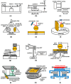
Main experiments of Casimir force. (a) Leverage system [43,44], (b) balanced levers system [33], (c) double cantilever spring system [3], (d) torsion pendulum system [48], (e) AFM system for plate–sphere [49,50,51,55,56,86,87], (f) AFM system for corrugated plate–sphere [75,76,88], (g) micromachined torsional devices [42,52,82,89], (h) fibre interferometer–cantilever system [41], (i) fibre interferometer–nanomembrane system [90], (j) piezoelectric tube–bimorph cantilever system [61], (k) vibrating plate system [91,92], (l) comb and amplifier system [84,85] (completely redrawn by the ideas of these references).
Figure 7
Figure 7
Shows the drying process in which the microshutters come together to form the Yin–Yang structure on the left-hand side, and on the right-hand side, an SEM micrograph of the resultant paired shutters. Modified from [64,65].
Figure 8
Figure 8
Left: Focused ion beam micrograph of the area where two microshutters come close together with a gap around 15 nm. Top right: Comsol simulation of the steps to estimate the distance d. (a) Un-actuated shutter, (b) un-actuated shutter (dotted) and shutter (full line) actuated via an external force Fext acting on the area A (its cross-section highlighted as a red stripe), (c) elastic force Felast and counteracting external force Fext on area A, (d) the identical force equilibrium with the same but shifted forces, (e) both shutters in grey overlapping within A (red), (f) force equilibrium for the right shutter: restoring elastic force Felast and counteracting Casimir force FC, acting on the right area A (red), (g) force equilibrium also involving forces acting on the left shutter and formation of a plate capacitor arrangement (red) with known area A and distance d to be determined. Bottom right: Model calculations of the obtained Casimir force densities depending on the distance between the shutter blades d for (1) the Casimir approach (red line), (2) the Hamaker approach (dashed blue line) and (3) the exact model (solid light blue line), respectively. Modified from [64].
Figure 9
Figure 9
Graph showing comparison between different forces including gravitational, electrostatic, capillary and Casimir (retarded and non retarded) forces based on the introduced model. On the horizontal axis is the separation distance between the metal plates and on the vertical axis is the force density. The black line represents the gravitational forces, the red line represents the electrostatic forces, the blue line represents the capillary forces, the green line represents Casimir forces in the retarded regime and the magenta is the Casimir forces in the nonretarded regime.
Figure 10
Figure 10
Paired shutter arrangement as checkerboard (a) and tubes (b). The pairing and the overlapping area between the shutter blades, A and B, and the fitted orange and blue ellipses to identify both of the shutter blades. The extracted fit parameters are the major and minor axes (c).

References

    1. Casimir H.B.G. On the attraction between two perfectly conducting plates. Proc. Kon. Ned. Akad. Wet. 1948;51:793–796.
    1. Casimir H.B.G., Polder D. The Influence of Retardation on the London-van der Waals Forces. Phys. Rev. 1948;73:360–372. doi: 10.1103/PhysRev.73.360. - DOI
    1. Israelachvili J.N., Tabor D. The measurement of van der Waals dispersion forces in the range 1.5 to 130 nm. Proc. R. Soc. Lond. A Math. Phys. Sci. 1972;331:19–38. doi: 10.1098/rspa.1972.0162. - DOI
    1. Palasantzas G., van Zwol P.J., De Hosson J.T.M. Transition from Casimir to van der Waals force between macroscopic bodies. Appl. Phys. Lett. 2008;93:121912. doi: 10.1063/1.2992030. - DOI
    1. Boström M., Sernelius B.E., Brevik I., Ninham B.W. Retardation turns the van der Waals attraction into a Casimir repulsion as close as 3 nm. Phys. Rev. A. 2012;85:010701. doi: 10.1103/PhysRevA.85.010701. - DOI

LinkOut - more resources