. 2024;4(1):13.
doi: 10.1186/s43593-024-00072-8. Epub 2024 Jul 24.

A source of entangled photons based on a cavity-enhanced and strain-tuned GaAs quantum dot

Affiliations

A source of entangled photons based on a cavity-enhanced and strain-tuned GaAs quantum dot

Michele B Rota et al. eLight. 2024.

Abstract

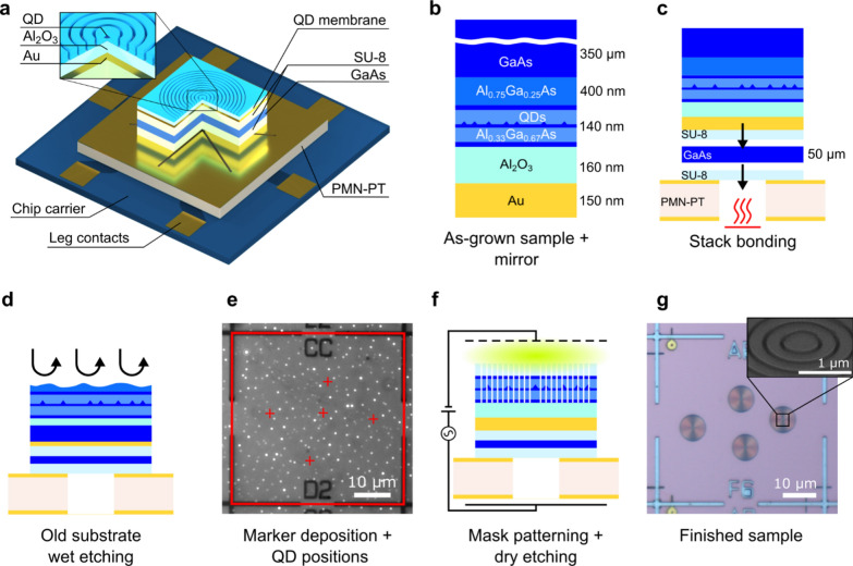
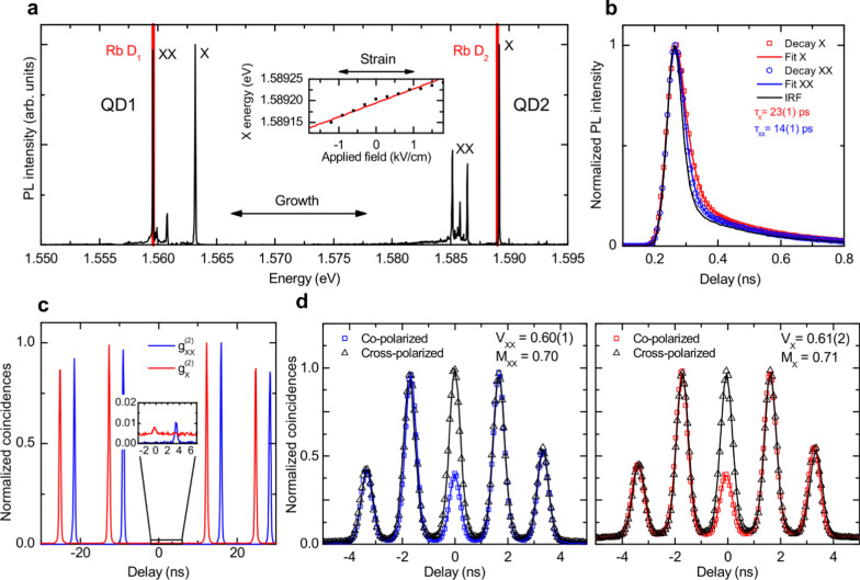
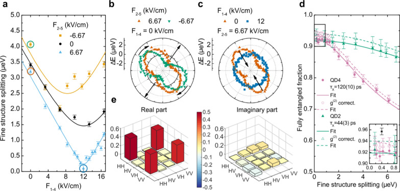
A quantum-light source that delivers photons with a high brightness and a high degree of entanglement is fundamental for the development of efficient entanglement-based quantum-key distribution systems. Among all possible candidates, epitaxial quantum dots are currently emerging as one of the brightest sources of highly entangled photons. However, the optimization of both brightness and entanglement currently requires different technologies that are difficult to combine in a scalable manner. In this work, we overcome this challenge by developing a novel device consisting of a quantum dot embedded in a circular Bragg resonator, in turn, integrated onto a micromachined piezoelectric actuator. The resonator engineers the light-matter interaction to empower extraction efficiencies up to 0.69(4). Simultaneously, the actuator manipulates strain fields that tune the quantum dot for the generation of entangled photons with corrected fidelities to a maximally entangled state up to 0.96(1). This hybrid technology has the potential to overcome the limitations of the key rates that plague QD-based entangled sources for entanglement-based quantum key distribution and entanglement-based quantum networks.

Supplementary information: The online version contains supplementary material available at 10.1186/s43593-024-00072-8.


Conflict of interest statement

Competing interestsThe authors declare no competing financial or non-financial interests.

Figures

Fig. 1
Fig. 1
Processing steps for fabricating a circular Bragg resonator (CBR) cavity on a piezoelectric substrate. a Schematic of a CBR sample on six-legged piezoelectric substrate mounted on a chip carrier. Dimensions are not to scale. b As-grown quantum dot (QD) sample structure with the oxide and metal mirror deposited on the surface. c The sample is bonded with SU-8 photoresist on a GaAs carrier by applying pressure and heat to reach the curing temperature of the photoresist (230 °C). The carrier is later lapped to reduce its thickness to approximately 50 µm. After thinning, the sample is bonded suspended onto the six-legged piezoelectric substrate by using the same procedure. d The original substrate and the sacrificial layer are removed via wet etching. e Cryogenic optical microscope image showing the photoluminescence of single QDs and a square grid of metallic markers defined on the sample surface via electron beam lithography (EBL) and metal deposition to create a frame of reference. The red square is the result of marker recognition obtained with image processing software. The red crosses represent the positions of single QDs obtained with a 2D Gaussian fit of the QD emission. f CBRs are defined in a second EBL step around preselected single QDs. The masked sample is then dry-etched with chlorine and argon plasma in an inductively coupled plasma machine to transfer the cavities onto the membrane. g Optical microscopy image of a finished sample. A tilted scanning electron microscope image of the centre of a single structure is shown in the inset
Fig. 2
Fig. 2
Optical characterization of cavity-enhanced QDs. a Photoluminescence spectra of two representative QDs (labelled QD1 and QD2) from two different samples showing emission in the vicinity of the D1 and D2 transitions of rubidium (Rb). The exciton (X) and biexciton (XX) transitions are labelled. The emission of the QD can be tuned toward the resonance of the Rb transitions with the application of stress, as shown in the inset. b Time-resolved traces of the X (red squares) and XX (blue circles) transition intensities via resonant two photon excitation (TPE) from the lowest lifetime QD (QD3) in the sample and instrument response function (IRF) (black solid line) of the setup. The lifetime values are obtained with a fit (solid lines) convoluting the IRF with the exponential decay functions expected from the radiative cascade. c g2τ histograms of the X (red line) and XX (blue line) emission lines for QD2. The histograms are shifted horizontally for ease of reading. The graphs around the 0-time delay are magnified in the inset to highlight the residual low coincidences. The values of the g(2)0 are gXX20=0.012(1) and gX20=0.016(1). d Histograms of Hong-Ou-Mandel interference between co- (red/blue squares) and cross-polarized (black triangles) photons from X and XX decay, respectively, from QD2. The values of the visibility V are obtained using Gaussian peaks convoluted with an exponential decay fit of the peaks (solid lines). The values for the indistinguishability MX=0.71 and MXX=0.70 are calculated by considering the imperfections of the setup and the values of the g(2)0, see text for more details
Fig. 3
Fig. 3
Entanglement recovery via strain-tuning of the QD. a Fine structure splitting (FSS) of the X level for different values of the electric field applied to legs 1and 4 of the piezoelectric device while varying the value of the electric field applied to legs 2 and 5. The solid lines are given as a guide to the eye. The differently coloured circled points correspond to the curves in the polar plots of panels b and c. b Polar plot of the distance of the X emission energy from its unperturbed value for two different fields on legs 2 and 5 of the device, while keeping the field value of legs 1 and 4 at 0 kV/cm. The straight arrows highlight the alleged strain direction while the curved arrows highlight the rotation of the polarization angle. c Same as b but for different values of the field of legs 1 and 4 of the device, while keeping the value of legs 2 and 5 at 6.67 kV/cm. d Fully entangled fraction, namely the maximum fidelity to a maximally entangled state versus the FSS, for the emitted photon pair of QD2 (green triangles) with higher Purcell factor (τX=443ps) and QD4 (pink circles) with lower Purcell factor (τX=120(10)ps). The hollow data points correspond to the same measurements corrected for the non-zero value of the g20. The solid and dashed lines are fits of the data, raw and g2-corrected respectively, using a simplified model of the FEF, see text. The black star point in the magnified inset is obtained by reducing the laser pulse length to 1.9(3) ps. e Reconstructed density matrix at the highest fully entangled fraction of QD2 of panel (d)

References

    1. D. Awschalom et al., Development of Quantum Interconnects (QuICs) for next-generation information technologies. PRX Quantum 2, 017002 (2021)10.1103/PRXQuantum.2.017002 - DOI
    1. D.A. Vajner, L. Rickert, T. Gao, K. Kaymazlar, T. Heindel, Quantum communication using semiconductor quantum dots. Adv. Quantum Technol. 5, 2100116 (2022)10.1002/qute.202100116 - DOI
    1. C.-Y. Lu, J.-W. Pan, Quantum-dot single-photon sources for the quantum internet. Nat. Nanotechnol. 16, 1294–1296 (2021) 10.1038/s41565-021-01033-9 - DOI - PubMed
    1. E. Pelucchi et al., The potential and global outlook of integrated photonics for quantum technologies. Nat. Rev. Phys. 4, 194–208 (2021)10.1038/s42254-021-00398-z - DOI
    1. R. Uppu, L. Midolo, X. Zhou, J. Carolan, P. Lodahl, Quantum-dot-based deterministic photon–emitter interfaces for scalable photonic quantum technology. Nat. Nanotechnol. 16, 1308–1317 (2021) 10.1038/s41565-021-00965-6 - DOI - PubMed

LinkOut - more resources