. 2021 Jun 1;7(6):93.
doi: 10.3390/jimaging7060093.

Volumetric Semantic Instance Segmentation of the Plasma Membrane of HeLa Cells

Affiliations

Volumetric Semantic Instance Segmentation of the Plasma Membrane of HeLa Cells

Cefa Karabağ et al. J Imaging. .

Abstract

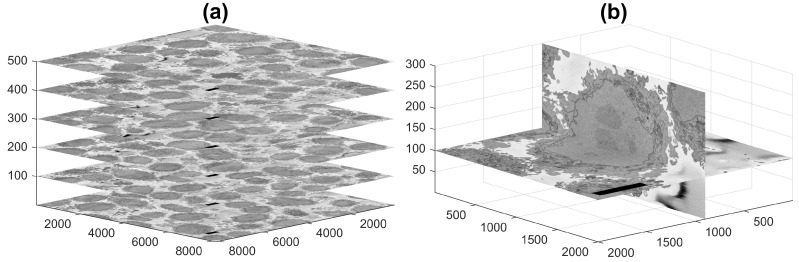
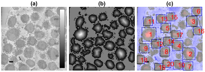
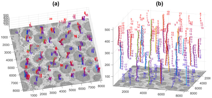
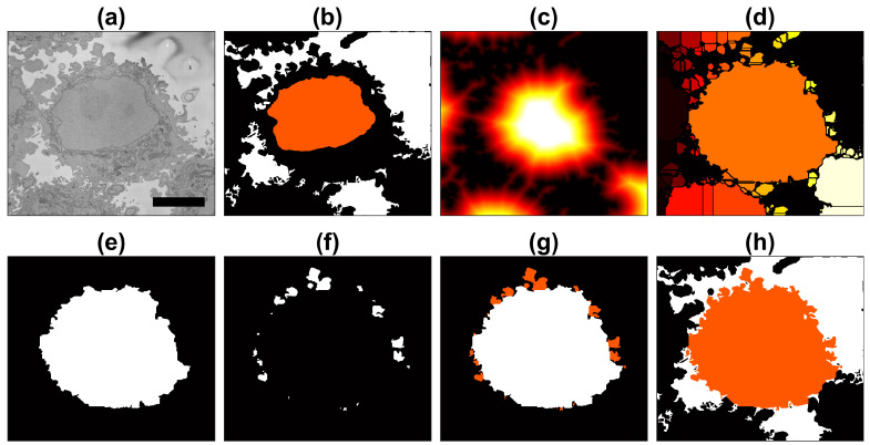
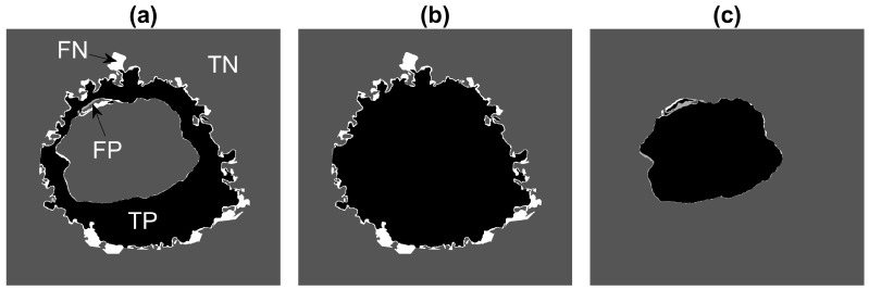
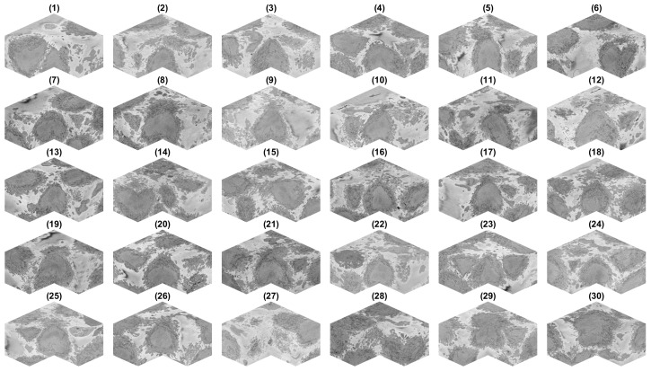
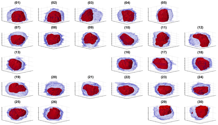
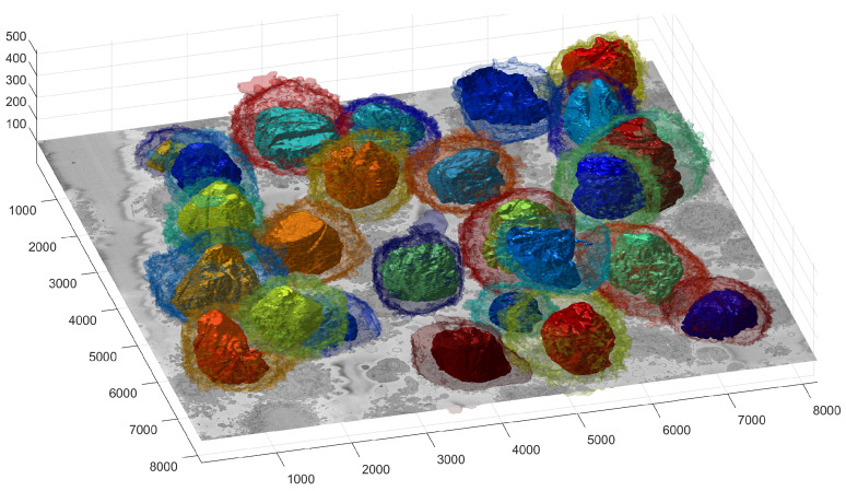
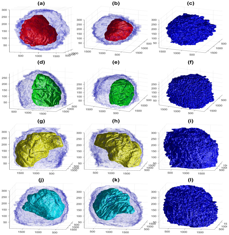
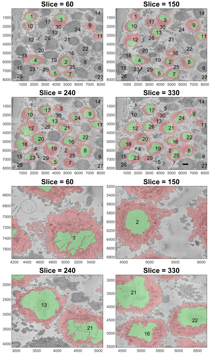
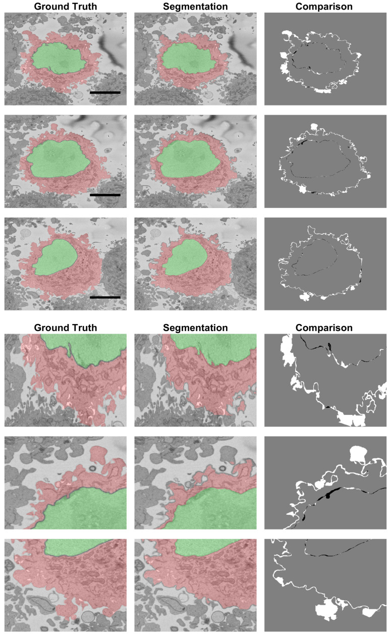
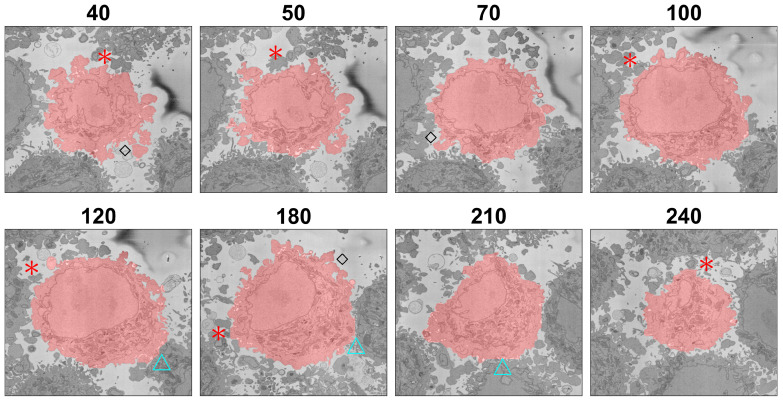
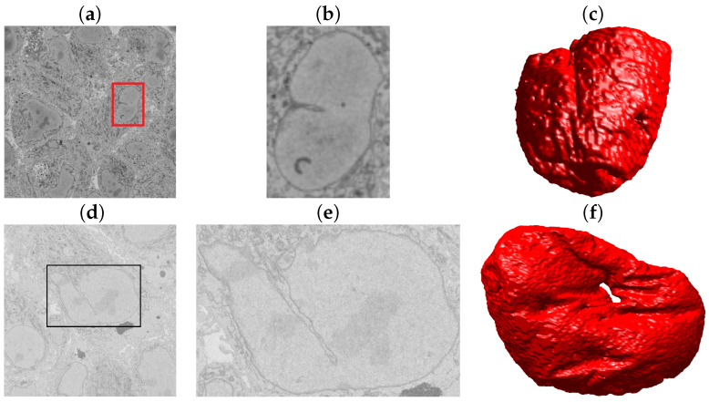
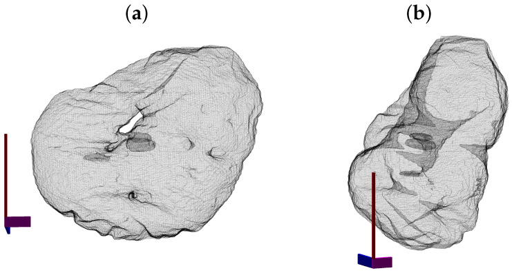
In this work, an unsupervised volumetric semantic instance segmentation of the plasma membrane of HeLa cells as observed with serial block face scanning electron microscopy is described. The resin background of the images was segmented at different slices of a 3D stack of 518 slices with 8192 × 8192 pixels each. The background was used to create a distance map, which helped identify and rank the cells by their size at each slice. The centroids of the cells detected at different slices were linked to identify them as a single cell that spanned a number of slices. A subset of these cells, i.e., the largest ones and those not close to the edges were selected for further processing. The selected cells were then automatically cropped to smaller regions of interest of 2000 × 2000 × 300 voxels that were treated as cell instances. Then, for each of these volumes, the nucleus was segmented, and the cell was separated from any neighbouring cells through a series of traditional image processing steps that followed the plasma membrane. The segmentation process was repeated for all the regions of interest previously selected. For one cell for which the ground truth was available, the algorithm provided excellent results in Accuracy (AC) and the Jaccard similarity Index (JI): nucleus: JI =0.9665, AC =0.9975, cell including nucleus JI =0.8711, AC =0.9655, cell excluding nucleus JI =0.8094, AC =0.9629. A limitation of the algorithm for the plasma membrane segmentation was the presence of background. In samples with tightly packed cells, this may not be available. When tested for these conditions, the segmentation of the nuclear envelope was still possible. All the code and data were released openly through GitHub, Zenodo and EMPIAR.

Keywords: HeLa cells; plasma membrane; semantic instance segmentation.


Conflict of interest statement

The authors declare no conflict of interest.

Figures

Figure 1
Figure 1
Representative slices of a 3D image stack acquired by Serial Block-face Scanning Electron Microscopy (SBF SEM) containing numerous HeLa cells. (a) Six of the stack of 518 of electron microscopy images. (b) For visualisation purposes, two slices of a HeLa cell image are presented orthogonal to each other. In both cases, the units of the axes are in voxels, and 5 μm scale bars are shown towards the left of all horizontal images.
Figure 2
Figure 2
Automatic identification of cells from 8192 × 8192 images. (a) One representative slice with many HeLa cells. The scale bar corresponds to 5 μm. (b) Illustration of the detected background (grey constant shade) and distance transform (grey to white) that corresponds to the cells; the larger the cell is, the brighter the intensity of the transform. (c) Composite image of the slice as in (a), background as a purple shade and 20 detected cells, ranked in order of size. It should be noted that smaller cells were not selected as there was a limit of 20 in the present example.
Figure 3
Figure 3
Centroids of cells that were identified per slice are displayed in three dimensions. Each number corresponds to the centroid of one cell that has been identified in a given slice. The numbers decrease according to the rank of the cell in that slice with 1 being the largest cell detected in that slice. The colour of the font varies from blue (lower slices) to red (higher slices) for visualisation purposes. A coloured line with a random colour is placed next to the centroids that were associated as a single cell. (a,b) show the same information from different points of view. The units of the axes are in voxels.
Figure 4
Figure 4
Illustration of the steps of the segmentation algorithm for a cell from neighbouring cells. (a) Region Of Interest (ROI) that contains one HeLa cell surrounded by background and other cells. (b) The algorithm starts with the nuclear region and background. (c) Distance transform from the background. (d) Watershed transformation on the distance transform; all regions in the background were removed. (e) Central region from the watershed. (f) Small regions that were contiguous to the central region. (g) Addition of small regions, i.e., membrane protuberances. (h) Final result of the cell with the background in white and neighbouring cells in black. A 5 μm scale bar is shown in (a).
Figure 5
Figure 5
Illustration of the pixel-based metrics. True Positives (TPs, black), True Negatives (TNs, dark grey), false Positives (FPs, light grey) and False Negatives (FNs, white) are presented with increasing grey level intensity. (a) Cellular region excluding nucleus. (b) Entire cellular region. (c) Nucleus. FNs are far more common than FPs in (a,b) as some convoluted regions of the cell were not segmented.
Figure 6
Figure 6
ROIs cropped from the volume. Thirty regions of interest were detected and cropped. For each region of interest, a corner was removed to show the cell, which should be centred. It should be noted that some cells were not in the centre, but rather positioned towards the bottom of the volume (e.g., 1), the top (e.g., 30) or the sides (e.g., 6,14,15,27,28).
Figure 7
Figure 7
Rendering of the cell and nuclear envelope (NE) of 25 cells. For each case, the NE is rendered in red without transparency, and the cell membrane is rendered in blue with transparency. The cells in ROIs 6,14,15,27 and 28 were located on the edges of the volume, and the centroids were too close to the edges and thus discarded. For comparison purposes, the cells were placed in the same locations as in Figure 6, and the ROIs that were discarded are blank.
Figure 8
Figure 8
Illustration of the segmentation of 25 cells and Nuclear Envelopes (NEs). The cells were segmented from a 8192 × 8192 × 518 voxel region. Slice Number 100 out of 518 is displayed for context. All nuclei are shown solid, and all cell membranes are shown as transparent; colours have been assigned randomly for visualisation purposes. The units of the axes are in voxels.
Figure 9
Figure 9
Four examples of the volumetric reconstruction of the NEs and the cell membranes of HeLa cells. In all cases, each row corresponds to a single cell observed from different view points. The left and centre columns show the cell membrane as transparent. The right column is the cell membrane without transparency from the same view point as the centre column. The volume of interest is 2000 × 2000 × 300 voxels, and the units of the axes are in voxels. (ac) ROI 23; the NE is shown in red and the cell in blue. Notice the relative smoothness except for one groove along the cell and the concentration on the lower part of the cell. (df) ROI 3; the NE is shown in green. Notice the ruggedness of the NE with numerous grooves and the concentration of the nucleus towards one side of the cell. (gi) ROI 12; NE is shown in yellow. Notice the distribution of the nucleus concentrated on the upper part of the cell. (jl) ROI 19; NE is shown in cyan. The surface of the NEs appears more distinctive than those of the cells.
Figure 10
Figure 10
Final illustration of the results in four representative slices. Cells are highlighted with a red shade, and the nuclei are highlighted with a green shade. Numbers were added to aid the localisation of the particular cell. Notice that some of the numbers corresponded to cells that were not visible in that particular slice. The units of the axes are in pixels, and a scale bar indicating 5 μm is shown in Slice 330 on the top. The bottom shows a magnified version of the slices.
Figure 11
Figure 11
Comparison between the Ground Truth (GT) and the segmentation result obtained from the segmentation algorithm shown in three slices of the stack. The left column illustrates the GT with shades of green for the nucleus and shades of red for the cell. The centre column shows the result of the segmentation algorithm. The right column shows the comparison between the GT and the results with FNs in white, FPs in black and both TPs and TNs in grey. Large white regions correspond to the distinction between neighbouring cells. A 5 μm scale bar is shown in the GTs on the top, and a magnification is shown below.
Figure 12
Figure 12
Illustration of the segmentation at several slices of one cell. The segmentation is indicated with a red shade over the cell. Red asterisks indicate regions where the segmentation did not include protuberances that could belong either to the cell or to neighbouring cells. Blue triangles indicate regions where two cells were close together and the segmentation tended to a straight line between the cells. Black diamonds indicate convoluted protuberances that were correctly segmented. The slice number relative to the stack of 300 is indicated above each slice.
Figure 13
Figure 13
Illustration of the Serial Block Face Scanning Electron Microscope (SBF SEM) images containing monolayers of Chlamydia trachomatis-infected HeLa cells. (a) A representative image from the Cell Image Library CIL50051 dataset. The volume has 3200×3200×413 voxels, and the voxel size is 3.6×3.6×60 nm. (b) An ROI with one nucleus, which corresponds to the red box in (a). (c) Rendering of the NE of this cell. (d) One representative image from the Cell Image Library CIL50061 dataset. The set has 2435×2489×406 voxels and a voxel size 8.6×8.6×60 nm. (e) An ROI with one nucleus corresponding to the black box in (d). (f) Rendering of the NE of this cell.
Figure 14
Figure 14
Illustration of the nuclear envelope from the dataset CIL50051. The surface is displayed as a mesh with transparency to show the hole of the nuclear envelope (a) and the crevices that go deep inside the nucleus. Notice in (b) how these invaginations nearly connect separate sides of the NE.

Similar articles

Cited by

References

    1. Masters J.R. HeLa cells 50 years on: The good, the bad and the ugly. Nat. Rev. Cancer. 2002;2:315–319. doi: 10.1038/nrc775. - DOI - PubMed
    1. Chesebro B., Wehrly K., Metcalf J., Griffin D.E. Use of a new CD4-positive HeLa cell clone for direct quantitation of infectious human immunodeficiency virus from blood cells of AIDS patients. J. Infect. Dis. 1991;163:64–70. doi: 10.1093/infdis/163.1.64. - DOI - PubMed
    1. Bich-Loan N.T., Kien K.T., Thanh N.L., Kim-Thanh N.T., Huy N.Q., The-Hai P., Muller M., Nachtergael A., Duez P., Thang N.D. Toxicity and Anti-Proliferative Properties of Anisomeles indica Ethanol Extract on Cervical Cancer HeLa Cells and Zebrafish Embryos. Life. 2021;11:257. doi: 10.3390/life11030257. - DOI - PMC - PubMed
    1. Li L., Collins N.D., Widen S.G., Davis E.H., Kaiser J.A., White M.M., Greenberg M.B., Barrett A.D.T., Bourne N., Sarathy V.V. Attenuation of Zika Virus by Passage in Human HeLa Cells. Vaccines. 2019;7:93. doi: 10.3390/vaccines7030093. - DOI - PMC - PubMed
    1. Kemet S. Insight Medicine Lacks—The Continuing Relevance of Henrietta Lacks. N. Engl. J. Med. 2019;381:800–801. doi: 10.1056/NEJMp1905346. - DOI - PubMed

LinkOut - more resources