. 2024 Aug 6;15(1):6691.
doi: 10.1038/s41467-024-50923-8.

Holographic direct sound printing

Affiliations

Holographic direct sound printing

Mahdi Derayatifar et al. Nat Commun. .

Abstract

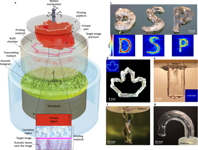
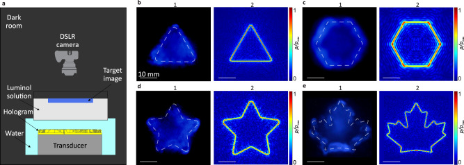
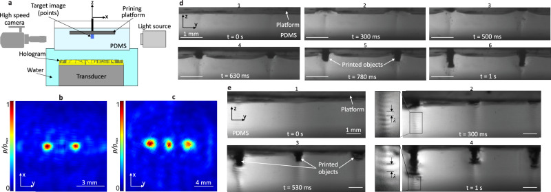
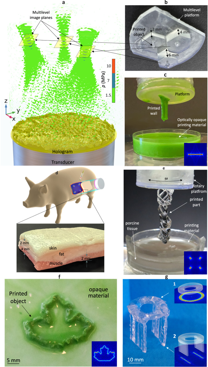
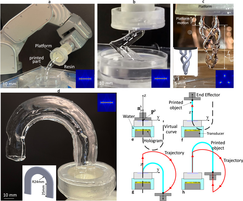
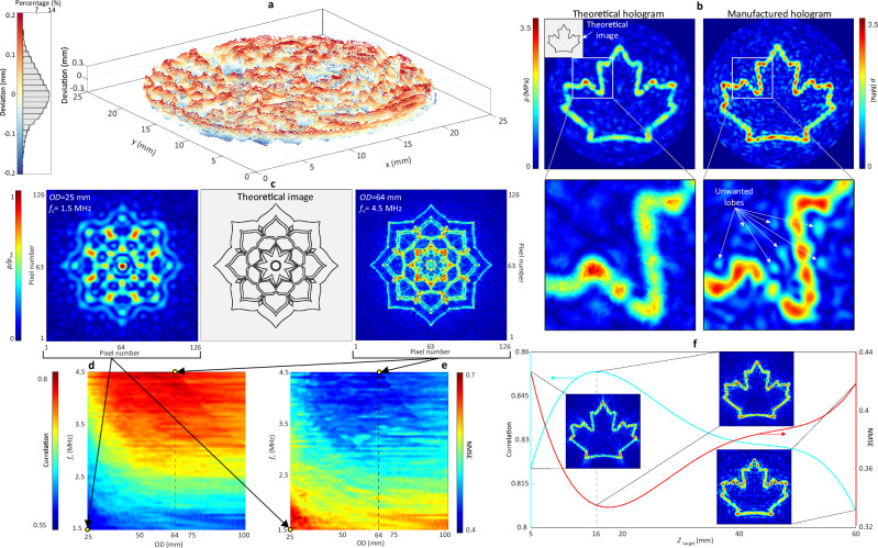
Direct sound printing (DSP), an alternative additive manufacturing process driven by sonochemical polymerization, has traditionally been confined to a single acoustic focal region, resulting in a voxel-by-voxel printing approach. To overcome this limitation, we introduce holographic direct sound printing (HDSP), where acoustic holograms, storing cross-sectional images of the desired parts, pattern acoustic waves to induce regional cavitation bubbles and on-demand regional polymerization. HDSP outperforms DSP in terms of printing speed by one order of magnitude and yields layerless printed structures. In our HDSP implementation, the hologram remains stationary while the printing platform moves along a three-dimensional path using a robotic arm. We present sono-chemiluminescence and high-speed imaging experiments to thoroughly investigate HDSP and demonstrate its versatility in applications such as remote ex-vivo in-body printing and complex robot trajectory planning. We showcase multi-object and multi-material printing and provide a comprehensive process characterization, including the effects of hologram design and manufacturing on the HDSP process, polymerization progression tracking, porosity tuning, and robotic trajectory computation. Our HDSP method establishes the integration of acoustic holography in DSP and related applications.


Conflict of interest statement

The authors declare the following competing interests: M.H. and M.P. are inventors of patents (US20200001533A1, US20230339181A1 and PCTCA2024050618). These patents are related to the topic covered in this manuscript. M.D. and R.B. declare no competing interests.

Figures

Fig. 1
Fig. 1. HDSP concept and printed objects.
a Schematic of HDSP process with the printed part on a platform mounted on a robotic end effector, showing the end-effector coordinate system (ECS) and translational (xyz) and rotational (ωx, ωy, ωz) degrees of freedom. b Detailed view of the printing region, cavitation bubbles are created near the target pressure image. c Printed “DSP” letters, printing parameters: P = 20 W, f0 = 2.28 MHz, DC = 35%, with their corresponding simulated pressure patterns, p, normalized to the maximum pressure, pmax. d Printed maple leaf, printing parameters: P = 25 W, OD = 50 mm, f0 = 2.28 MHz, DC = 30%. e Fully transparent printed wall axially extruded/printed by feed, f, along +z-axis, printing parameters: P = 6 W, OD = 25 mm, f0 = 2.24 MHz, DC = 20%. f Transparent printed helix by translational and rotational motions of the platform in multi-axis HDSP. g Self-supported U-shape object printed via computed robot trajectory using the same printing condition as (e). OD, P, f0 and DC are transducer aperture size, acoustic power, acoustic center frequency and duty cycle, respectively.
Fig. 2
Fig. 2. SCL experiments to demonstrate the patternability of chemical reactions using holograms.
a SCL setup including a DSLR camera capturing top view of the luminol solution surface. b1e1 Captured luminol illumination patterns. b2e2 Corresponding theoretical acoustic pressure map at the target plane. Acoustic parameters used in (b) are OD = 25 mm, f0 = 2.24 MHz, DC = 100%, P = 15 W, in (c) are OD = 35 mm, f0 = 1.86 MHz, DC = 100%, P = 20 W, and in (d, e) are OD = 50 mm, f0 = 2.28 MHz, DC = 100%, P = 25 W.
Fig. 3
Fig. 3. Close observation of the HDSP printing process employing high-speed imaging.
a Side view of the observation setup including a high-speed camera to capture the HDSP printing process. b, c Normalized measured pressure maps of designed two- and three-spot pressure images, respectively. The gap between each two spots is 3 mm in (b) and 4 mm in (c). d Footage of high-speed imaging for two spots being printed with HDSP process during 1 s insonication. e Footage of high-speed imaging for three-spot printing during 1 s insonication. In all cases the platform (image plane) is designed to be 20 mm away from the transducer, printing parameters: OD = 25 mm, P = 5 W, f0 = 2.24 MHz, DC = 50%.
Fig. 4
Fig. 4. Especial Applications of HDSP.
a Simulated pressure field of multi-target image planes creating multiple spots in one shot. b Printed various spots in one shot on multi-level platform using a single acoustic hologram. c Printing in non-transparent material enabling remote distance printing (RDP) applications. d Schematic of the idea of on-invasive printing within a living organism through the RDP concept. The zoomed view details the porcine tissue layers employed in the RDP experiment. e Printed twisted helix over the barrier including porcine tissue shown in (d). Printing parameters: OD = 25 mm, P = 8 W, f0 = 2.24 MHz, DC = 50%. f Printed maple leaf in non-transparent material as another example of RDP. Printing parameters: OD = 50 mm, P = 25 W, f0 = 2.85 MHz, DC = 50%. g An example of overprinting possibility in HDSP, where two walls are printed over the printed hollow circular shell. The fabrication steps are shown in g1 and 2.
Fig. 5
Fig. 5. Robot-assisted HDSP.
a Experimental setup comprising a printing platform which is mounted to a robotic arm’s end-effector and an arc being printed with the corresponding pressure pattern. b An object with the in-plane extrusion path. c Helical object created by rotation about the z-axis with variable feed while being extruded in +z-direction with constant feed. The pressure pattern used is shown in the inset. The inset shows the 3D model of the intended part. d Unsupported U-shape part formed with computed robot trajectory. e–h Schematic of the printing process of (d) and computed trajectory.
Fig. 6
Fig. 6. Hologram-related process characterization of HDPS.
a Surface deviation and deviation distribution between manufactured and theoretical holograms. b Pressure patterns obtained via finite element analysis for the theoretical hologram (b-left) and scanned manufactured hologram (b-right). c Image and printing resolution investigation by changing OD and f0, a theoretical mandala image (c-center) is constructed in low resolution (c-left) by OD = 25 mm, f0 = 1.5 MHz and high resolution (c-right) by OD = 64 mm, f0 = 4.5 MHz. d, e Correlation and NMSE with respect to OD and f0 for the theoretical mandala image (c-center). f The image plane location, Ztarget, and its effect on Correlation and NMSE.

References

    1. Habibi, M., Foroughi, S., Karamzadeh, V. & Packirisamy, M. Direct sound printing. Nat. Commun.13, 1800 (2022). 10.1038/s41467-022-29395-1 - DOI - PMC - PubMed
    1. Melchels, F. P. W., Feijen, J. & Grijpma, D. W. A review on stereolithography and its applications in biomedical engineering. Biomaterials31, 6121–6130 (2010). 10.1016/j.biomaterials.2010.04.050 - DOI - PubMed
    1. Gissibl, T., Thiele, S., Herkommer, A. & Giessen, H. Two-photon direct laser writing of ultracompact multi-lens objectives. Nat. Photonics10, 554–560 (2016).10.1038/nphoton.2016.121 - DOI
    1. Kim, Y. T., Ahmadianyazdi, A. & Folch, A. A ‘print–pause–print’ protocol for 3D printing microfluidics using multimaterial stereolithography. Nat. Protoc.18, 1243–1259 (2023). 10.1038/s41596-022-00792-6 - DOI - PMC - PubMed
    1. Rahim, T. N. A. T., Abdullah, A. M., & Md Akil, H. Recent developments in fused deposition modeling-based 3D printing of polymers and their composites. Polym. Rev.59, 589–624 (2019).10.1080/15583724.2019.1597883 - DOI

LinkOut - more resources