Computerized Surgical Planning in Face Transplantation
- PMID: 39118859
- PMCID: PMC11305830
- DOI: 10.1055/s-0044-1786991
Computerized Surgical Planning in Face Transplantation
Abstract
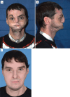
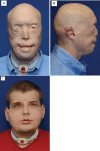
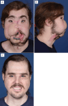
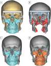
Face transplantation (FT) has emerged as a critical intervention for patients with complex facial deformities unsuitable for conventional reconstructive methods. It aims to restore essential functions such as facial expression, mastication, and speech, while also improving psychosocial health. The procedure utilizes various surgical principles, addressing unique challenges of craniofacial complexity and diverse injury patterns. The integration of Computerized Surgical Planning (CSP) leverages computer-aided technologies to enhance preoperative strategy, intraoperative navigation, and postoperative assessment. CSP utilizes three-dimensional computed tomography, printing, angiography, and navigation systems, enabling surgeons to anticipate challenges and reduce intraoperative trial and error. Through four clinical cases, including a groundbreaking combined face and bilateral hand transplant, CSP's role in FT is highlighted by its ability to streamline operative processes and minimize surgical revisions. The adoption of CSP has led to fewer cadaveric rehearsals, heightened operative precision, and greater alignment with preoperative plans. Despite CSP's advancements, it remains complementary to, rather than a replacement for, clinical expertise. The demand for technological resources and multidisciplinary teamwork is high, but the improved surgical outcomes and patient quality of life affirm CSP's value in FT. The technology has become a staple in reconstructive surgery, signaling a step forward in the evolution of complex surgical interventions.
Keywords: CSP; Computerized Surgical Planning; VCA; face transplant; facial reconstruction; facial trauma; transplant; vascularized composite allografts.
Thieme. All rights reserved.
Conflict of interest statement
Conflict of Interest None declared.
Figures







Similar articles
-
Computerized Approach to Facial Transplantation: Evolution and Application in 3 Consecutive Face Transplants.Plast Reconstr Surg Glob Open. 2019 Aug 19;7(8):e2379. doi: 10.1097/GOX.0000000000002379. eCollection 2019 Aug. Plast Reconstr Surg Glob Open. 2019. PMID: 31592022 Free PMC article.
-
Total face, double jaw, and tongue transplant simulation: a cadaveric study using computer-assisted techniques.Plast Reconstr Surg. 2012 Oct;130(4):815-823. doi: 10.1097/PRS.0b013e318262f2c9. Plast Reconstr Surg. 2012. PMID: 22691839
-
The First Successful Combined Full Face and Bilateral Hand Transplant.Plast Reconstr Surg. 2022 Aug 1;150(2):414-428. doi: 10.1097/PRS.0000000000009369. Epub 2022 Jun 9. Plast Reconstr Surg. 2022. PMID: 35674521
-
Virtual Surgical Planning and 3D-Printed Surgical Guides in Facial Allotransplantation.Semin Plast Surg. 2022 Dec 7;36(3):199-208. doi: 10.1055/s-0042-1756452. eCollection 2022 Aug. Semin Plast Surg. 2022. PMID: 36506279 Free PMC article. Review.
-
The evolution of three-dimensional technology in musculoskeletal oncology.J Clin Orthop Trauma. 2018 Jul-Sep;9(3):269-274. doi: 10.1016/j.jcot.2018.07.020. Epub 2018 Jul 25. J Clin Orthop Trauma. 2018. PMID: 30202160 Free PMC article. Review.
References
-
- Rifkin W J, David J A, Plana N M et al.Achievements and challenges in facial transplantation. Ann Surg. 2018;268(02):260–270. - PubMed
-
- Vyas K, Bakri K, Gibreel W, Cotofana S, Amer H, Mardini S. Facial Transplantation. Facial Plast Surg Clin North Am. 2022;30(02):255–269. - PubMed
-
- Coffman K L, Gordon C, Siemionow M. Psychological outcomes with face transplantation: overview and case report. Curr Opin Organ Transplant. 2010;15(02):236–240. - PubMed
-
- Meningaud J P, Hivelin M, Benjoar M D, Toure G, Hermeziu O, Lantieri L. The procurement of allotransplants for ballistic trauma: a preclinical study and a report of two clinical cases. Plast Reconstr Surg. 2011;127(05):1892–1900. - PubMed
Publication types
LinkOut - more resources
Full Text Sources

