

NeuroRoots, a bio-inspired, seamless brain machine interface for long-term recording in delicate brain regions
- PMID: 39130131
- PMCID: PMC11309783
- DOI: 10.1063/5.0216979
NeuroRoots, a bio-inspired, seamless brain machine interface for long-term recording in delicate brain regions
Abstract
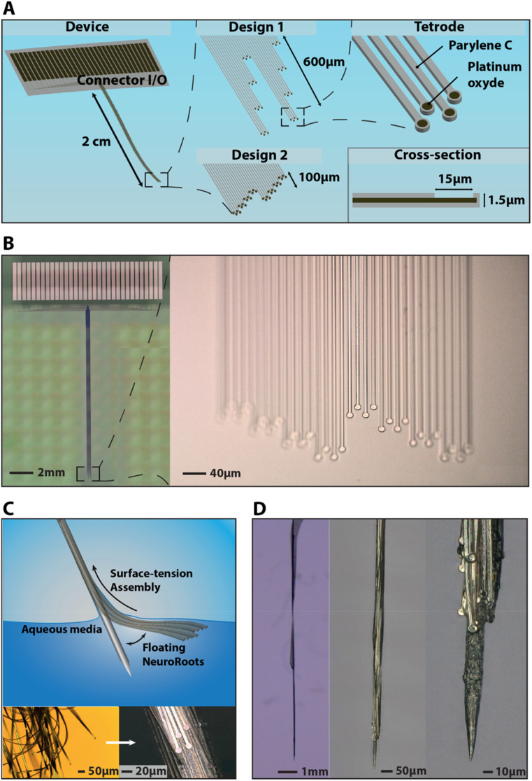
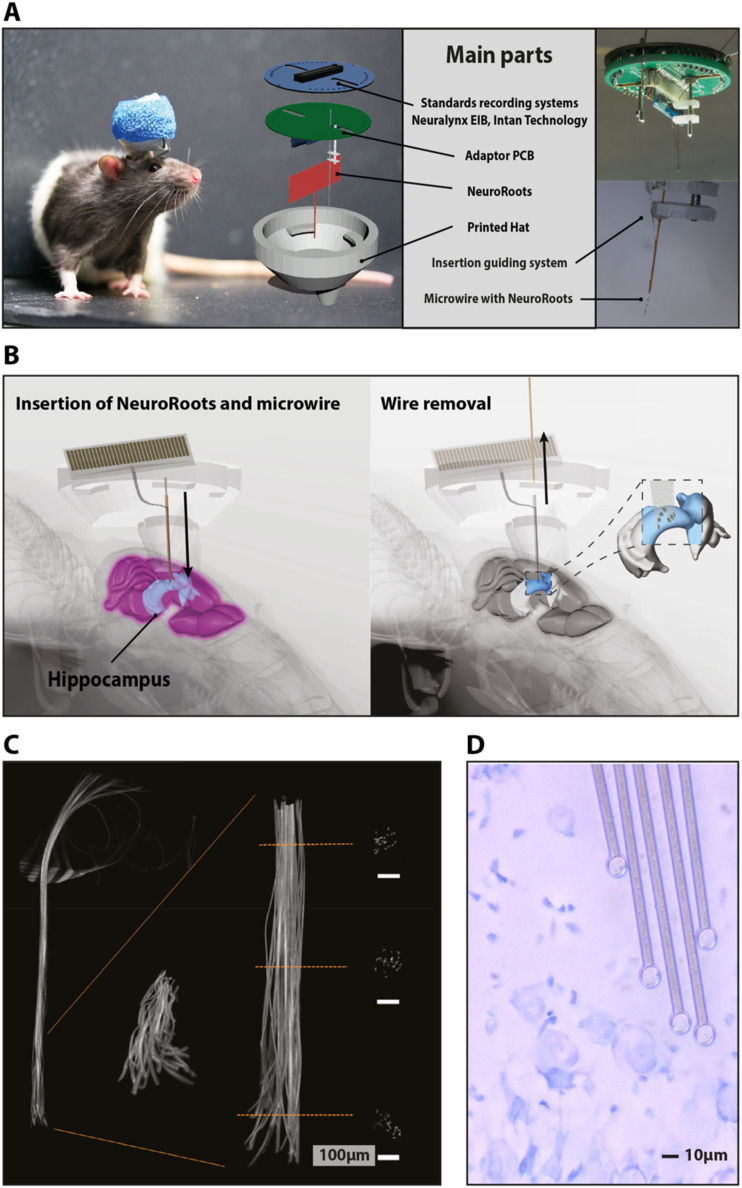
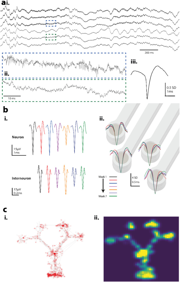
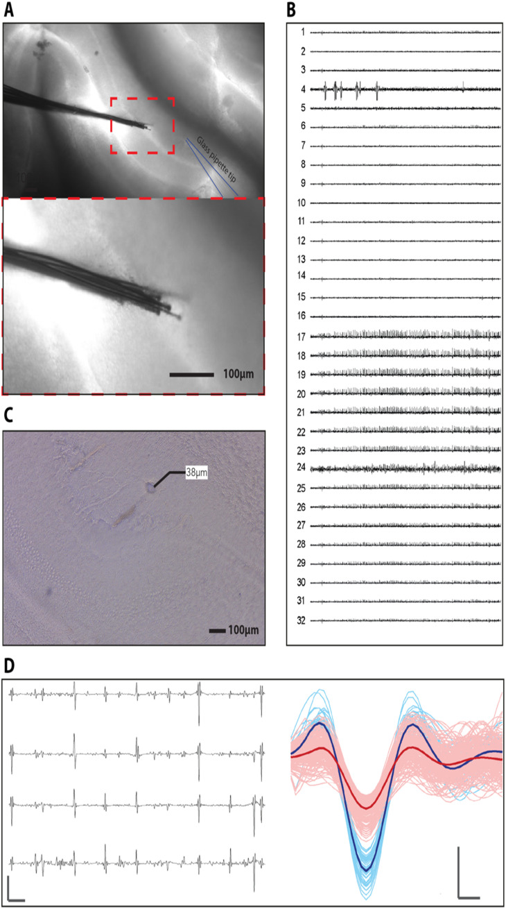
Scalable electronic brain implants with long-term stability and low biological perturbation are crucial technologies for high-quality brain-machine interfaces that can seamlessly access delicate and hard-to-reach regions of the brain. Here, we created "NeuroRoots," a biomimetic multi-channel implant with similar dimensions (7 μm wide and 1.5 μm thick), mechanical compliance, and spatial distribution as axons in the brain. Unlike planar shank implants, these devices consist of a number of individual electrode "roots," each tendril independent from the other. A simple microscale delivery approach based on commercially available apparatus minimally perturbs existing neural architectures during surgery. NeuroRoots enables high density single unit recording from the cerebellum in vitro and in vivo. NeuroRoots also reliably recorded action potentials in various brain regions for at least 7 weeks during behavioral experiments in freely-moving rats, without adjustment of electrode position. This minimally invasive axon-like implant design is an important step toward improving the integration and stability of brain-machine interfacing.
© 2024 Author(s).
Conflict of interest statement
The authors have no conflicts to disclose.
Figures
Similar articles
-
Mesh Nanoelectronics: Seamless Integration of Electronics with Tissues.Acc Chem Res. 2018 Feb 20;51(2):309-318. doi: 10.1021/acs.accounts.7b00547. Epub 2018 Jan 30. Acc Chem Res. 2018. PMID: 29381054 Free PMC article.
-
Optimizing the neuron-electrode interface for chronic bioelectronic interfacing.Neurosurg Focus. 2020 Jul;49(1):E7. doi: 10.3171/2020.4.FOCUS20178. Neurosurg Focus. 2020. PMID: 32610294
-
A mosquito mouthpart-like bionic neural probe.Microsyst Nanoeng. 2023 Jul 12;9:88. doi: 10.1038/s41378-023-00565-5. eCollection 2023. Microsyst Nanoeng. 2023. PMID: 37448967 Free PMC article.
-
How is flexible electronics advancing neuroscience research?Biomaterials. 2021 Jan;268:120559. doi: 10.1016/j.biomaterials.2020.120559. Epub 2020 Dec 2. Biomaterials. 2021. PMID: 33310538 Free PMC article. Review.
-
Implantable neurotechnologies: a review of micro- and nanoelectrodes for neural recording.Med Biol Eng Comput. 2016 Jan;54(1):23-44. doi: 10.1007/s11517-015-1430-4. Epub 2016 Jan 11. Med Biol Eng Comput. 2016. PMID: 26753777 Review.
Cited by
-
Implantable intracortical microelectrodes: reviewing the present with a focus on the future.Microsyst Nanoeng. 2023 Jan 5;9:7. doi: 10.1038/s41378-022-00451-6. eCollection 2023. Microsyst Nanoeng. 2023. PMID: 36620394 Free PMC article. Review.
-
Flexible multimaterial fibers in modern biomedical applications.Natl Sci Rev. 2024 Sep 23;11(10):nwae333. doi: 10.1093/nsr/nwae333. eCollection 2024 Oct. Natl Sci Rev. 2024. PMID: 39411353 Free PMC article. Review.
-
Bioinspired Materials for In Vivo Bioelectronic Neural Interfaces.Matter. 2020 Oct 7;3(4):1087-1113. doi: 10.1016/j.matt.2020.08.002. Matter. 2020. PMID: 33103115 Free PMC article.
-
The future of transcranial ultrasound as a precision brain interface.PLoS Biol. 2024 Oct 29;22(10):e3002884. doi: 10.1371/journal.pbio.3002884. eCollection 2024 Oct. PLoS Biol. 2024. PMID: 39471185 Free PMC article.
-
Neuronal activity in the ventral tegmental area during goal-directed navigation recorded by low-curvature microelectrode arrays.Microsyst Nanoeng. 2024 Oct 14;10(1):145. doi: 10.1038/s41378-024-00778-2. Microsyst Nanoeng. 2024. PMID: 39396959 Free PMC article.
References
Grants and funding
LinkOut - more resources
Full Text Sources