Review
. 2024 Jul 31:12:1401613.
doi: 10.3389/fbioe.2024.1401613. eCollection 2024.

Unpacking the packaged optical fiber bio-sensors: understanding the obstacle for biomedical application

Affiliations
Review

Unpacking the packaged optical fiber bio-sensors: understanding the obstacle for biomedical application

Aidana Bissen et al. Front Bioeng Biotechnol. .

Abstract

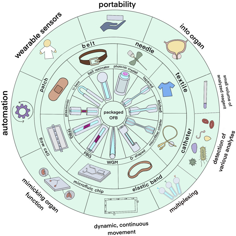
A biosensor is a promising alternative tool for the detection of clinically relevant analytes. Optical fiber as a transducer element in biosensors offers low cost, biocompatibility, and lack of electromagnetic interference. Moreover, due to the miniature size of optical fibers, they have the potential to be used in microfluidic chips and in vivo applications. The number of optical fiber biosensors are extensively growing: they have been developed to detect different analytes ranging from small molecules to whole cells. Yet the widespread applications of optical fiber biosensor have been hindered; one of the reasons is the lack of suitable packaging for their real-life application. In order to translate optical fiber biosensors into clinical practice, a proper embedding of biosensors into medical devices or portable chips is often required. A proper packaging approach is frequently as challenging as the sensor architecture itself. Therefore, this review aims to give an unpack different aspects of the integration of optical fiber biosensors into packaging platforms to bring them closer to actual clinical use. Particularly, the paper discusses how optical fiber sensors are integrated into flow cells, organized into microfluidic chips, inserted into catheters, or otherwise encased in medical devices to meet requirements of the prospective applications.

Keywords: biosensor; microfluidic; optical fiber; packaged; wearable.


Conflict of interest statement

The authors declare that the research was conducted in the absence of any commercial or financial relationships that could be construed as a potential conflict of interest. The author(s) declared that they were an editorial board member of Frontiers, at the time of submission. This had no impact on the peer review process and the final decision.

Figures

FIGURE 1
FIGURE 1
An overview of packaged optical fiber bio-sensors. The inner circle depicts the types of optical fiber sensors; the middle circle shows the types of packages used to integrate the sensors while the outer circle shows potential application areas.
FIGURE 2
FIGURE 2
Flow cells as part of experimental setups employing optical fiber biosensors. (i) (A) An experimental setup of the packaged sensor system. (B) Nanoplasmonic sensor chips were functionalized with Protein A for specific recognition of IgG. Adapted from (Tran et al., 2020) (ii) (C) An experimental setup consisting of the multi-microchannel sensing system. The multi-microchannel biochip was composed of two PMMA plates, a cover and a bottom plate, with dimensions of 40 mm × 30 mm × 4 mm and fabricated by using a CO2 laser. Adapted from (Chiang et al., 2020), (iii) (D) An experimental setup consisting of the thermo-stabilized flow cell system. The aluminum bottom part of the flow cell is mounted in thermal contact with a Peltier cell (20 mm) and a thermistor is inserted into the lateral hole. Adapted from (Cennamo et al., 2016). All images licensed under Creative Commons CC BY 4.0.
FIGURE 3
FIGURE 3
Various designs and fabrication approaches of microfluidic chips. (i) (A) Project of the two PDMS layers of the microfermentor. (B) Layers and acrylic molds before the fermentor assembly. (C) Micro Fermenter before the insertion and sealing of the optical fibers. (D) schematic diagram of the micro fermenter: top-level (i) cover (glass), and (ii) microchannels (PDMS laminated); and bottom-level (iii) membranes (polycarbonate), (iv) intermediate sheet with holes (PDMS laminated), and (v) base (glass). Adapted from (Soares et al., 2019). (ii) Representation of the molding process and completion of the microchip with mounting OFS. (E) PDMS in mold before heat processing and top layer bubble removal. (F) PDMS sensor after fabrication with light and pneumatic circuit. Adapted from (Sannino et al., 2023). (iii) (upper) Chip structure and (lower) Real etched chip. The four microfluidic channels branches were designed for inlets and outlets of bio-target and fluid, respectively. Adapted from (Tian et al., 2011), All images licensed under Creative Commons CC BY 4.0.
FIGURE 4
FIGURE 4
Optical fiber biosensors are packaged into medical devices such as catheters, syringes, and needles. (i) (A) Schematic of the multiplexing methodology of the NPDFs. (B) The upper view of the fiber mount on the needle. (C) The schematic of the fiber arrangement on the needle. (D) An experimental setup comprising the fibers glued along the epidural needle and connected to the Luna OBR interrogator via the splitter. (E) Backscattering trace of the OBR in proximity of the 4-fiber sensing setup. Adapted from (Amantayeva et al., 2021). (ii) (F) The developed guiding device comprises a standard 20 G nylon EC integrated inside the lumen of an epidural needle. (G) The FBG is inserted inside the catheter lumen and locked in position. Adapted from (Carotenuto et al., 2018). (iii) Sensor package structure. Integration of OFS into the hollow needle. Adapted from (Zhao et al., 2021). All images licensed under Creative Commons CC BY 4.0.
FIGURE 5
FIGURE 5
Optical fiber biosensors packaged into wearable devices. (i) (A) Twisting and (B) bending of the silicone layer embedding the FBG sensor; (C) the smart patch backend and (D) frontend. Adapted from (Lo Presti et al., 2022). (ii) (E) Schematic diagram of FBG sensor integration. A glove is fitted with five serialized sensing arrays containing FBG sensors. (F) attitude reconfiguration system comprising five parallel FBG arrays connected to the five channels of the FBG demodulator. Adapted from (Rao et al., 2023). (iii) (G) photograph of the wearable swallowing assessment device with fabricated hetero-core fiber-optic pressure sensor attached to a neck belt. (H) appearance when a user attaches the wearable swallowing assessment device. The belt was used to apply a stable level of pressure between the larynx and the device. Adapted from (Maeda et al., 2023). All images licensed under Creative Commons CC BY 4.0.
FIGURE 6
FIGURE 6
A variety of analytes detected or studied by the packaged optical fiber biosensors. * - virus or viral protein. (A) (Tolosa et al., 1999; Tang et al., 2002; Endo et al., 2006; Tseng et al., 2007; Tian et al., 2011; Weidemaier et al., 2011; Evers et al., 2012; Thakkar et al., 2013; Guo et al., 2014; Barucci et al., 2015; Lin et al., 2015; Nguyen et al., 2015; Wang et al., 2015; Amin et al., 2016; Chauhan et al., 2016; Lee et al., 2018; Tyagi et al., 2018; Afsarimanesh et al., 2020; Wen et al., 2022; Kundu et al., 2024); (B) (Nguyen et al., 2015; Khatri et al., 2018; Zhou et al., 2018; Tran et al., 2020; Bekmurzayeva et al., 2021; Bekmurzayeva et al., 2022; Qu et al., 2022; Sypabekova et al., 2022; Wen et al., 2022); (C) (Hsu et al., 2011; Fan et al., 2016; Mustapha Kamil et al., 2018; Kamil et al., 2019); (D) (Verma and Gupta, 2013; Kaushik et al., 2019; Soni et al., 2021); (E) (Haddock et al., 2003; Fan et al., 2016; Semwal and Gupta, 2018; Usha and Gupta, 2018; Olmos et al., 2019; Vogelbacher et al., 2022); (F) (Evers et al., 2012; Semwal and Gupta, 2018; Qu et al., 2022; Xu et al., 2022).

Similar articles

Cited by

  • Photodynamic particle pump in microfluidic systems.
    Du J, Yuan T, Zhang X, Zhang K, Zhu F, Chen W, Tang X, Xiao C, Yuan L. Du J, et al. Biomed Opt Express. 2025 Mar 11;16(4):1392-1405. doi: 10.1364/BOE.555270. eCollection 2025 Apr 1. Biomed Opt Express. 2025. PMID: 40321990 Free PMC article.

References

    1. Abdul Hamid I. S. L., Mustapha Kamil Y., Abd Manaf A., Mahdi M. A. (2017). Fabrication and characterization of micro fluidic based fiber optic refractive index sensor. Sens. Biosensing Res. 13, 70–74. 10.1016/j.sbsr.2017.03.003 - DOI
    1. Afsarimanesh N., Nag A., Sarkar S., Sabet G. S., Han T., Mukhopadhyay S. C. (2020). A review on fabrication, characterization and implementation of wearable strain sensors. Sens. Actuators A Phys. 315, 112355. 10.1016/j.sna.2020.112355 - DOI
    1. Amantayeva A., Adilzhanova N., Issatayeva A., Blanc W., Molardi C., Tosi D. (2021). Fiber optic distributed sensing network for shape sensing-assisted epidural needle guidance. Biosens. (Basel) 11, 446. 10.3390/bios11110446 - DOI - PMC - PubMed
    1. Amin R., Knowlton S., Hart A., Yenilmez B., Ghaderinezhad F., Katebifar S., et al. (2016). 3D-printed microfluidic devices. Biofabrication 8, 022001. 10.1088/1758-5090/8/2/022001 - DOI - PubMed
    1. Arasu P. T., Noor A. S. M., Shabaneh A. A., Yaacob M. H., Lim H. N., Mahdi M. A. (2016). Fiber Bragg grating assisted surface plasmon resonance sensor with graphene oxide sensing layer. Opt. Commun. 380, 260–266. 10.1016/j.optcom.2016.05.081 - DOI

LinkOut - more resources