. 2024 Aug 22;19(1):499.
doi: 10.1186/s13018-024-05006-1.

Stochastic lattice-based porous implant design for improving the stress transfer in unicompartmental knee arthroplasty

Affiliations

Stochastic lattice-based porous implant design for improving the stress transfer in unicompartmental knee arthroplasty

Tao Deng et al. J Orthop Surg Res. .

Abstract

Background: Unicompartmental knee arthroplasty (UKA) has been proved to be a successful treatment for osteoarthritis patients. However, the stress shielding caused by mismatch in mechanical properties between human bones and artificial implants remains as a challenging issue. This study aimed to properly design a bionic porous tibial implant and evaluate its biomechanical effect in reconstructing stress transfer pathway after UKA surgery.

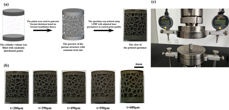
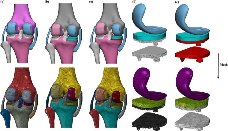
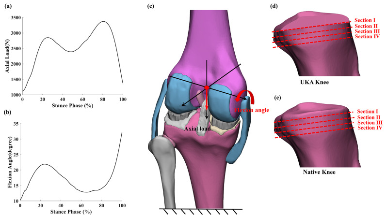
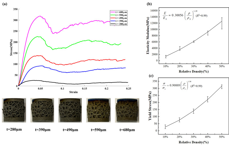
Methods: Voronoi structures with different strut sizes and porosities were designed and manufactured with Ti6Al4V through additive manufacturing and subjected to quasi-static compression tests. The Gibson-Ashby model was used to relate mechanical properties with design parameters. Subsequently, finite element models were developed for porous UKA, conventional UKA, and native knee to evaluate the biomechanical effect of tibial implant with designed structures during the stance phase.

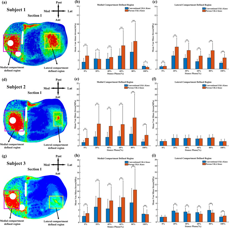
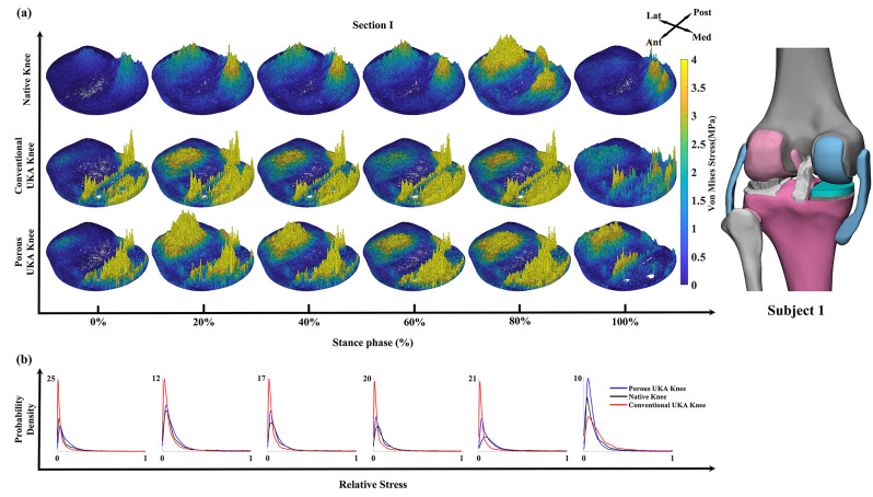
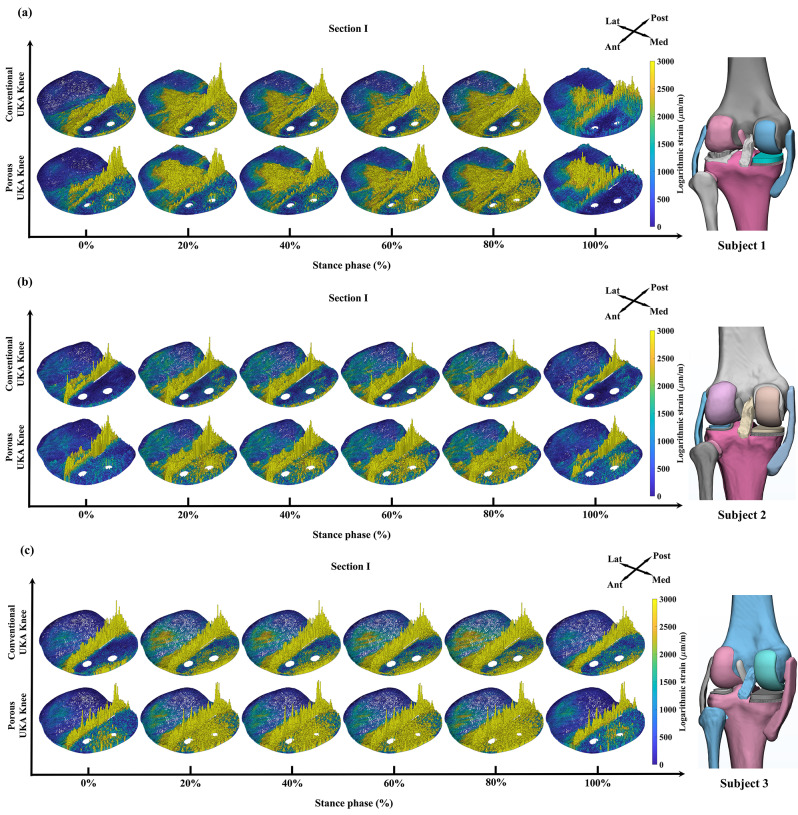
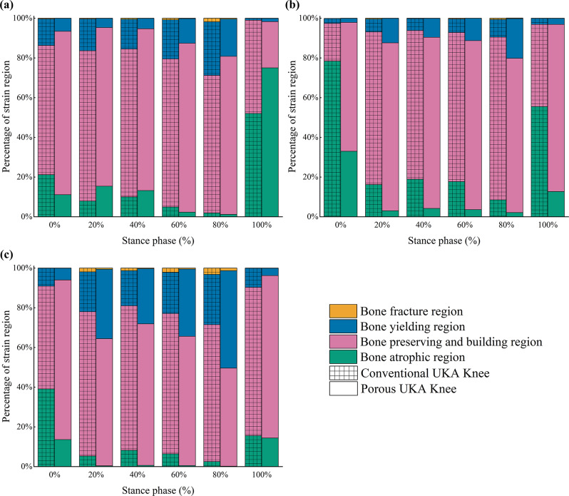
Results: The internal stress distribution on the tibia plateau in the medial compartment of the porous UKA knee was found to closely resemble that of the native knee. Furthermore, the mean stress values in the medial regions of the tibial plateau of the porous UKA knee were at least 44.7% higher than that of the conventional UKA knee for all subjects during the most loading conditions. The strain shielding reduction effect of the porous UKA knee model was significant under the implant and near the load contact sites. For subject 1 to 3, the average percentages of nodes in bone preserving and building region (strain values range from 400 to 3000 μm/m) of the porous UKA knee model, ranging from 68.7 to 80.5%, were higher than that of the conventional UKA knee model, ranging from 61.6 to 68.6%.

Conclusions: The comparison results indicated that the tibial implant with designed Voronoi structure offered better biomechanical functionality on the tibial plateau after UKA. Additionally, the model and associated analysis provide a well-defined design process and dependable selection criteria for design parameters of UKA implants with Voronoi structures.

Keywords: Additive manufacturing; Bone stress transfer pathway; Finite element analysis; Porous implants; Unicompartmental knee arthroplasty.


Conflict of interest statement

The authors declare no competing interests.

Figures

Fig. 1
Fig. 1
The Voronoi structure design and manufacturing: (a) Design and manufacturing workflow of the porous structure. (b) Five specimens were manufactured with different strut sizes. (c) Quasi-static compression test setup
Fig. 2
Fig. 2
Finite element (FE) models: (a) Native knee model; (b) Porous UKA knee model; (c) Conventional UKA knee model; (d) Porous UKA prosthesis components; (e) Conventional UKA prosthesis components
Fig. 3
Fig. 3
The loading conditions used in the comparison test for the native knee, conventional UKA knee, and porous UKA knee FE models: (a) Axial load during the stance phase. (b) Flexion angle during the stance phase. (c) Loading positions in the native knee FE model (the loading positions in UKA knee FE models are the same). The positions of four different sections on the tibial plateau in (d) the UKA knee FE model and (e) the Native knee FE model
Fig. 4
Fig. 4
Mean von Mises stress on section I (on the surface of the tibial plateau, with a thickness of 1 mm) of the porous and conventional UKA knee finite element (FE) models during the stance phase: (a)(d)(g) Definition of the stress comparison regions: the medial compartment defined region (left, indicated by a purple quadrangle with 20 × 20 mm, 22 × 20 mm, and 22 × 18 mm for subject 1 to 3 respectively) and the lateral compartment defined region (right, indicated by a yellow quadrangle with 18 × 18 mm, 16 × 10 mm, and 14 × 16 mm for subject 1 to 3 respectively). Mean von Mises stress in the (b)(e)(h) medial and (c)(f)(i) lateral tibial compartment-defined regions of two knee FE models. (Ant: Anterior; Post: Posterior; Lat: Lateral; Med: Medial. Error bars indicate standard deviations. Asterisks (* and **) indicate the difference (p < 0.05) and significant difference (p < 0.01), respectively)
Fig. 5
Fig. 5
Stress-strain curves and fitting curves of the Quasi-static compression test: (a) Compression Stress-Strain Curves for five specimens with different strut diameters. Correlation of relative density to (b) elastic modulus and (c) yield stress based on the Gibson-Ashby model. (R2 values for all curve fits are 0.99. Relative density formula image= 1- porosity)
Fig. 6
Fig. 6
Qualitative analysis of section I (on the surface of the tibial plateau with a thickness of 1 mm) of the native, porous UKA, and conventional UKA knee finite element models (Subject 1) during the stance phase: (a) The von Mises stress distribution of section I and (b) probability density function (PDF) maps related to stress values from section I. (Ant: Anterior; Post: Posterior; Lat: Lateral; Med: Medial)
Fig. 7
Fig. 7
The logarithmic strain distribution of section I (on the surface of the tibial plateau with a thickness of 1 mm) of the porous UKA and conventional UKA knee finite element models for (a) subject 1, (b) subject 2, and (c) subject 3 during the stance phase. (Ant: Anterior; Post: Posterior; Lat: Lateral; Med: Medial)
Fig. 8
Fig. 8
Fraction of four divided strain regions divided by strain-dependent bone remodeling assumptions in tibial medial compartment of Section I (the surface of the tibial plateau, with a thickness of 1 mm) for conventional and porous UKA knee finite element models for (a) subject 1, (b) subject 2, and (c) subject 3 during the stance phase

Similar articles

References

    1. Newman J, Pydisetty RV, Ackroyd C. Unicompartmental or total knee replacement: the 15-year results of a prospective randomised controlled trial. J Bone Joint Surg Br. 2009;91(1):52–7. 10.1302/0301-620X.91B1.20899 - DOI - PubMed
    1. Sangaletti R, Andriollo L, Montagna A, Are L, Benazzo F, Rossi SMP. Lateral UKA can be a safe solution in a young patients’ population: a 10-year follow-up report. Arch Orthop Trauma Surg. 2024. - PubMed
    1. Mikkelsen M, Wilson HA, Gromov K, Price AJ, Troelsen A. Comparing surgical strategies for end-stage anteromedial osteoarthritis TOTAL VERSUS UNICOMPARTMENTAL KNEE ARTHROPLASTY. Bone Joint Open. 2022;3(5):441–7. 10.1302/2633-1462.35.BJO-2021-0174.R1 - DOI - PMC - PubMed
    1. Rossi SMP, Perticarini L, Clocchiatti S, Ghiara M, Benazzo F. Mid- to long-term follow-up of combined small implants. Bone Joint J. 2021;103–B(5):840–5. 10.1302/0301-620X.103B5.BJJ-2020-0720.R3 - DOI - PubMed
    1. Rossi SMP, Sangaletti R, Nesta F, Matascioli L, Terragnoli F, Benazzo F. A well performing medial fixed bearing UKA with promising survivorship at 15 years. Arch Orthop Trauma Surg. 2022;143(5):2693–9. 10.1007/s00402-022-04562-7 - DOI - PubMed

LinkOut - more resources