Review
. 2022 Dec 22;1(1):e20220001.
doi: 10.1002/SMMD.20220001. eCollection 2022 Dec.

Microfluidic technologies for cell deformability cytometry

Affiliations
Review

Microfluidic technologies for cell deformability cytometry

Hanxu Chen et al. Smart Med. .

Abstract

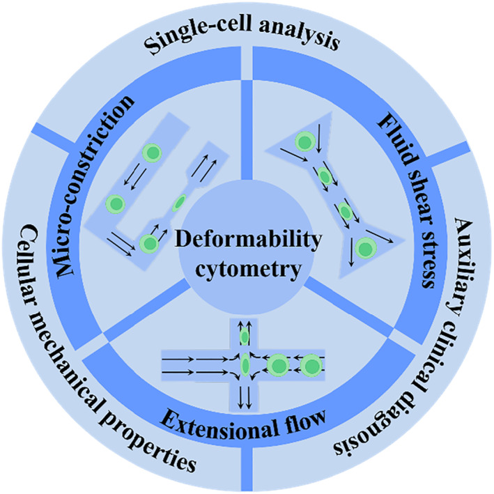
Microfluidic detection methods for cell deformability cytometry have been regarded as powerful tools for single-cell analysis of cellular mechanical phenotypes, thus having been widely applied in the fields of cell preparation, separation, clinical diagnostics and so on. Featured with traits like easy operations, low cost and high throughput, such methods have shown great potentials on investigating physiological state and pathological changes during cellular deformation. Herein, a review on the advancements of microfluidic-based cell deformation cytometry is presented. We discuss several representative microfluidic-based cell deformability cytometry methods with their frontiers in practical applications. Finally, we analyze the current status and propose the remaining challenges with future perspectives and development directions.

Keywords: biomechanical; deformability cytometry; high‐throughput; microfluidic; single‐cell.


Conflict of interest statement

There are no conflicts to declare. Yuanjin Zhao is a member of the Smart Medicine editorial board.

Figures

FIGURE 1
FIGURE 1
Scheme of the microfluidic‐based deformability cytometry methods and biomedical applications.
FIGURE 2
FIGURE 2
The schematic operation principles of three types of microfluidic technologies for cell deformability cytometry, including constriction deformability cytometry (A), fluid shear deformability cytometry (B), and extensional flow deformability cytometry (C). The bottom rows represent the typical signals of each method. Reproduced under terms of the CC‐BY license. Copyright 2020, The Authors, published by Springer Nature.
FIGURE 3
FIGURE 3
Optical imaging of the cell deformation process. (A) Scheme (i) and time sequence (ii) of a single cell passaging through the micron‐constriction with a pressure‐driven flow. (iii‐v) The characteristic parameters achieved during deformation. Reproduced with permission. Copyright 2017, Biophysical Society. (B) (i) Schematic representation of a red blood cell traversing across the microchannel. (ii) The experimental images (left) and simulation (right) data of the cellular shape during the traversing process. (iii) Bilayer–cytoskeletal detachment for the cell at different elastic interactions. Reproduced with permission. Copyright 2014, The Authors, published by the Royal Society.
FIGURE 4
FIGURE 4
Practical applications of cDCs. (A) (i) The structure and working mechanism of the microfluidic cell squeezer. A balanced interface in the comparator region between the fluids in the reference and test channels. (ii) The curve between excess pressure drop and time. The optical images of different states of the interface within the squeezer corresponding to the cellular deformations. Reproduced with permission. Copyright 2013, AIP Publishing. (B) (i) The scheme of the biophysical flow cytometer device. (ii) This visual tracking of neutrophil. The images of neutrophil transiting through microchannels before (iii) and after (iv) exposure to the inflammatory mediator increases. Reproduced with permission. Copyright 2008, The Royal Society of Chemistry.
FIGURE 5
FIGURE 5
Simulation models and applications of the sDC. (A) The setup of the channel geometry for sDC measurements (i) and the flow field around an advected sphere (ii). Reproduced with permission. Copyright 2015, The Authors, published by Elsevier Inc. (B) The cellular shapes for the elastic solid model and 3D illustration of the dent at the cell. Reproduced with permission. Copyright 2017, American Chemical Society. (C) The microfluidic device for multi‐sample deformability cytometry. (i) Optical images of the device embedded with microchannels, sample reservoirs, pressure controller, and microfluidic manifold. (ii) Scheme of the experimental setup. The right panel is the bright field image of cells traveling through the channels. Reproduced under terms of the CC‐BY license. Copyright 2018, The Authors, published by AIP Publishing. (D) (i) The 3D illustration of the silicon‐on‐insulator RIC device. (ii) Numerical simulation of the cell interaction with optical modes and the reference spherical cell. Reproduced with permission. Copyright 2019, The Royal Society of Chemistry.
FIGURE 6
FIGURE 6
Typical working principle and applications of xDC. (A) (i) The photograph of the microscope‐mounted and fluid‐coupled microfluidic deformability cytometry device. (ii) The structures of microchannels focusing cells before delivering them to the stretching extensional flow. (iii) The scheme of the cellular deformation within an extensional flow previously aligned at an inertial focusing position. (iv) Microscopic images of a single cell entering the extensional region. (v) Definitions of the shape parameters extracted from images. (vi) Density scatter plot of deformability measurements of single human embryonic stem cells. Reproduced under terms of the CC‐BY license. Copyright 2012, The Authors, published by National Academy of Sciences. (B) (i) Scheme of the cross‐flow channel geometry and cellular deformation under the velocity profiles. (ii) The velocity distribution within the extensional region without the cell present. (iii) The numerical simulation of the cellular shape changes through the cross‐flow channel. (iv) Comparison of the experimental and numerical deformation indexes of cells. Reproduced with permission. Copyright 2020, Biophysical Society. (C) The schematic diagram of the microfluidic device for analysis of four parameters during cellular deformation process. (ii) High‐speed photography of the deformation. (iii) Visualization of physical phenotypic spaces occupied by iPSCs, NSCs, and neurons. Reproduced under terms of the CC‐BY license. Copyright 2017, The Authors, published by Springer Nature. (D) (i) The scheme of the hydropipetting method possessing specific microchannel configurations for three working patterns. (ii) Overlaid images of a single cellular deformation including relaxing, and then deforming again in the extensional flow. Reproduced with permission. Copyright 2013, The Royal Society of Chemistry.

References

    1. Darling E. M., Di Carlo D., Annu. Rev. Biomed. Eng. 2015, 17, 35. - PMC - PubMed
    1. Li H., Torab P., Mach K. E., Surrette C., England M. R., Craft D. W., Thomas N. J., Liao J. C., Puleo C., Wong P. K., Proc. Natl. Acad. Sci. U S A 2019, 116, 10270. - PMC - PubMed
    1. Wang G., Crawford K., Turbyfield C., Lam W., Alexeev A., Sulchek T., Lab Chip 2015, 15, 532. - PubMed
    1. Sengul E., Elitas M., Micromachines 2020, 11, 845. - PMC - PubMed
    1. Polacheck W. J., Chen C. S., Nat. Methods 2016, 13, 415. - PMC - PubMed

LinkOut - more resources