. 2024 Jul 25;15(8):953.
doi: 10.3390/mi15080953.

Electrical Capacitors Based on Silicone Oil and Iron Oxide Microfibers: Effects of the Magnetic Field on the Electrical Susceptance and Conductance

Affiliations

Electrical Capacitors Based on Silicone Oil and Iron Oxide Microfibers: Effects of the Magnetic Field on the Electrical Susceptance and Conductance

Ioan Bica et al. Micromachines (Basel). .

Abstract

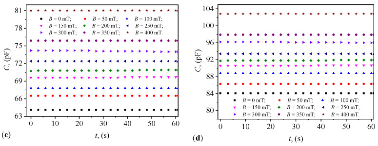
This paper presents the fabrication and characterization of plane capacitors utilizing magnetodielectric materials composed of magnetizable microfibers dispersed within a silicone oil matrix. The microfibers, with a mean diameter of about 0.94 μm, comprise hematite (α-Fe2O3), maghemite (γ-Fe2O3), and magnetite (Fe3O4). This study investigates the electrical behavior of these capacitors under the influence of an external magnetic field superimposed on a medium-frequency alternating electric field, across four distinct volume concentrations of microfibers. Electrical capacitance and resistance measurements were conducted every second over a 60-s interval, revealing significant dependencies on both the quantity of magnetizable phase and the applied magnetic flux density. Furthermore, the temporal stability of the capacitors' characteristics is demonstrated. The obtained data are analyzed to determine the electrical conductance and susceptance of the capacitors, elucidating their sensitivity to variations in microfiber concentration and magnetic field strength. To provide theoretical insight into the observed phenomena, a model based on dipolar approximations is proposed. This model effectively explains the underlying physical mechanisms governing the electrical properties of the capacitors. These findings offer valuable insights into the design and optimization of magnetodielectric-based capacitors for diverse applications in microelectronics and sensor technologies.

Keywords: electrical capacitors; electrical conductance; electrical susceptance; iron oxide microfibers; magnetic field; silicone oil.


Conflict of interest statement

The authors declare no conflicts of interest.

Figures

Figure A1
Figure A1
(a) SEM image of microfibers. (b) SEM image of microfibers with points (in red) where their thickness was measured. (c) Histogram of the thickness (diameter) of the microfibers (light blue columns) together with a Gaussian fit (red continuous line).
Figure A2
Figure A2
Microfibers (orange-brown aggregates) in SO (light blue). (a) Without any external field. (b) In the presence of a small magnetic field (about 20 mT).
Figure 1
Figure 1
(a) PCB. 1—copper foil. (b) Cylinder. 1—copper foil, 2—dielectric ring.
Figure 2
Figure 2
(a) Cylinder with CL. 1—copper foil, 3—CL, 4—electrical contact. (b) Cylinder with CL and with textolite plate on top. 2—dielectric ring, 5—textolite plates. (c) PEC. 6—adhesive medical tape. 7—terminals for electrical contact.
Figure 3
Figure 3
Schematic view of the experimental setup. 1—magnetic yoke, 2—coil, DCS—direct current source, Br—RLC bridge, Gs—Gauss meter, h—Hall probe, CU—computing unit, PEC—electrical capacitor based on CL, B—magnetic flux density vector.
Figure 4
Figure 4
Variation in capacitance over time at different values of magnetic flux density. (a) PEC1. (b) PEC2. (c) PEC3. (d) PEC4.
Figure 4
Figure 4
Variation in capacitance over time at different values of magnetic flux density. (a) PEC1. (b) PEC2. (c) PEC3. (d) PEC4.
Figure 5
Figure 5
Variation in resistance over time at different values of magnetic flux density. (a) PEC1. (b) PEC2. (c) PEC3. (d) PEC4.
Figure 6
Figure 6
A cross-sectional view of the PEC in equivalent electrical representation. (a,c) Without a magnetic field. (b,d) With a magnetic field. Cz0i and Czi are electrical micro-capacitors. Rz0i and Rzi are electrical micro-resistors. Yz0i and Yzi are the admittance of micro-capacitors. Cu—copper foil electrodes.
Figure 7
Figure 7
Model of a cross-sectional view of the PEC, without (a) and with (b) a magnetic field. P—iron oxide microparticles, SO—silicone oil, Cu—copper plates, D—diameter of PEC, h0—height of PEC, B and m—magnetic flux density vector, and, respectively, dipolar electric moment, δi and zi—distances between the center of masses of microparticles P within the CL, Oz—coordinate axis.
Figure 8
Figure 8
Variation with time of the susceptance of PECs, at different values of the magnetic flux density. (a) PEC1. (b) PEC2. (c) PEC3. (d) PEC4.
Figure 9
Figure 9
Variation with time of the conductance of PECs, at different values of the magnetic flux density. (a) PEC1. (b) PEC2. (c) PEC3. (d) PEC4.
Figure 10
Figure 10
Variation with magnetic flux density of the susceptance (a) and conductance (b) for PECs.
Figure 11
Figure 11
Variation of viscosity ηB with magnetic flux density (a), and with magnetic flux density and conductance (b) for PECs.
Figure 12
Figure 12
(a) Variation of average conductance Gm with average susceptance Bm for PECs. (b) Variation in the time constant with magnetic flux density for PECs. The black arrow indicates the direction of increase of the magnetic field density in the (Gm,Bm) plane.

References

    1. Ariyarathna T., Kularatna N., Gunawardane K., Jayananda D., Steyn-Ross D.A. Development of Supercapacitor Technology and Its Potential Impact on New Power Converter Techniques for Renewable Energy. IEEE J. Emerg. Sel. Top. Ind. Electr. 2021;2:267–276. doi: 10.1109/JESTIE.2021.3061962. - DOI
    1. Subasinghage K., Gunawardane K., Padmawansa N., Kularatna N., Moradian M. Modern Supercapacitors Technologies and Their Applicability in Mature Electrical Engineering Applications. Energies. 2022;15:7752. doi: 10.3390/en15207752. - DOI
    1. Laadjal K., Cardoso A.J.M. Multilayer Ceramic Capacitors: An Overview of Failure Mechanisms, Perspectives, and Challenges. Electronics. 2023;12:1297. doi: 10.3390/electronics12061297. - DOI
    1. Abid D., Mjejri I., Oueslati A., Guionneau P., Pechev S., Daro N., Elaoud Z. A Nickel-Based Semiconductor Hybrid Material with Significant Dielectric Constant for Electronic Capacitors. ACS Omega. 2024;9:12743–12752. doi: 10.1021/acsomega.3c08499. - DOI - PMC - PubMed
    1. Chaban V.V., Andreeva N.A. Higher hydrogen fractions in dielectric polymers boost self-healing in electrical capacitors. Phys. Chem. Chem. Phys. 2024;26:3184–3196. doi: 10.1039/D3CP05355E. - DOI - PubMed

LinkOut - more resources