Enhancing Magnetic Micro- and Nanoparticle Separation with a Cost-Effective Microfluidic Device Fabricated by Laser Ablation of PMMA
- PMID: 39203709
- PMCID: PMC11356012
- DOI: 10.3390/mi15081057
Enhancing Magnetic Micro- and Nanoparticle Separation with a Cost-Effective Microfluidic Device Fabricated by Laser Ablation of PMMA
Abstract
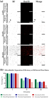
Superparamagnetic iron oxide micro- and nanoparticles have significant applications in biomedical and chemical engineering. This study presents the development and evaluation of a novel low-cost microfluidic device for the purification and hyperconcentration of these magnetic particles. The device, fabricated using laser ablation of polymethyl methacrylate (PMMA), leverages precise control over fluid dynamics to efficiently separate magnetic particles from non-magnetic ones. We assessed the device's performance through Multiphysics simulations and empirical tests, focusing on the separation of magnetite nanoparticles from blue carbon dots and magnetite microparticles from polystyrene microparticles at various total flow rates (TFRs). For nanoparticle separation, the device achieved a recall of up to 93.3 ± 4% and a precision of 95.9 ± 1.2% at an optimal TFR of 2 mL/h, significantly outperforming previous models, which only achieved a 50% recall. Microparticle separation demonstrated an accuracy of 98.1 ± 1% at a TFR of 2 mL/h in both simulations and experimental conditions. The Lagrangian model effectively captured the dynamics of magnetite microparticle separation from polystyrene microparticles, with close agreement between simulated and experimental results. Our findings underscore the device's robust capability in distinguishing between magnetic and non-magnetic particles at both micro- and nanoscales. This study highlights the potential of low-cost, non-cleanroom manufacturing techniques to produce high-performance microfluidic devices, thereby expanding their accessibility and applicability in various industrial and research settings. The integration of a continuous magnet, as opposed to segmented magnets in previous designs, was identified as a key factor in enhancing magnetic separation efficiency.
Keywords: CFD; SWOT; magnetite; microfluidic; purification; separation.
Conflict of interest statement
The authors declare that the research was conducted in the absence of any commercial or financial relationships that could be construed as potential conflicts of interest.
Figures


Similar articles
-
Low-cost inertial microfluidic device for microparticle separation: A laser-Ablated PMMA lab-on-a-chip approach without a cleanroom.HardwareX. 2023 Nov 11;16:e00493. doi: 10.1016/j.ohx.2023.e00493. eCollection 2023 Dec. HardwareX. 2023. PMID: 38045919 Free PMC article.
-
Zweifach-Fung Microfluidic Device for Efficient Microparticle Separation: Cost-Effective Fabrication Using CO2 Laser-Ablated PMMA.Micromachines (Basel). 2024 Jul 22;15(7):932. doi: 10.3390/mi15070932. Micromachines (Basel). 2024. PMID: 39064443 Free PMC article.
-
[Research progress in the application of external field separation technology and microfluidic technology in the separation of micro/nanoscales].Se Pu. 2021 Nov;39(11):1157-1170. doi: 10.3724/SP.J.1123.2020.12032. Se Pu. 2021. PMID: 34677011 Free PMC article. Review. Chinese.
-
Microfluidic device based on a micro-hydrocyclone for particle-liquid separation.Lab Chip. 2011 Dec 7;11(23):4012-21. doi: 10.1039/c1lc20606k. Epub 2011 Oct 26. Lab Chip. 2011. PMID: 22028066
-
Microfluidic Synthesis, Control, and Sensing of Magnetic Nanoparticles: A Review.Micromachines (Basel). 2021 Jun 29;12(7):768. doi: 10.3390/mi12070768. Micromachines (Basel). 2021. PMID: 34210058 Free PMC article. Review.
Cited by
-
Design, Characterization, and Evaluation of Textile Systems and Coatings for Sports Use: Applications in the Design of High-Thermal Comfort Wearables.ACS Omega. 2024 Nov 28;9(50):49143-49162. doi: 10.1021/acsomega.4c05600. eCollection 2024 Dec 17. ACS Omega. 2024. PMID: 39713610 Free PMC article.
-
A Sliding Microfluidic Chip-Integrated Colorimetric Biosensor Using MnO2 Nanoflowers for Rapid Salmonella Detection.Micromachines (Basel). 2025 Jul 31;16(8):904. doi: 10.3390/mi16080904. Micromachines (Basel). 2025. PMID: 40872411 Free PMC article.
-
A mathematical phase field model predicts superparamagnetic nanoparticle accelerated fusion of HeLa spheroids for field guided biofabrication.Sci Rep. 2025 Jun 5;15(1):19765. doi: 10.1038/s41598-025-04495-2. Sci Rep. 2025. PMID: 40473770 Free PMC article.
References
-
- Xiang W., Sun Y., Li L., Wang X., Zhao M., Dai C. Long Carbon Chain-Modified Carbon Nanoparticles for Oil Displacement in Harsh-Condition Reservoirs. J. Mol. Liq. 2024;406:125039. doi: 10.1016/j.molliq.2024.125039. - DOI
Grants and funding
LinkOut - more resources
Full Text Sources
Medical
Miscellaneous

