. 2024 Aug 12;24(16):5214.
doi: 10.3390/s24165214.

A Polymer Thick Film on an Organic Substrate Grid Electrode and an Open-Source Recording System for UHF MRI: An Imaging Study

Affiliations

A Polymer Thick Film on an Organic Substrate Grid Electrode and an Open-Source Recording System for UHF MRI: An Imaging Study

Yinching Iris Chen et al. Sensors (Basel). .

Abstract

Electrocorticography (ECoG) is a critical tool in preclinical neuroscience research for studying global network activity. However, integrating ECoG with functional magnetic resonance imaging (fMRI) has posed challenges, due to metal electrode interference with imaging quality and heating around the metallic electrodes. Here, we introduce recent advancements in ECoG grid development that utilize a polymer-thick film on an organic substrate (PTFOS). PTFOS offers notable advantages over traditional ECoG grids. Firstly, it significantly reduces imaging artifacts, ensuring minimal interference with MR image quality when overlaying brain tissue with PTFOS grids. Secondly, during a 30-min fMRI acquisition, the temperature increase associated with PTFOS grids is remarkably low, measuring only 0.4 °C. These findings suggest that utilizing ECoG with PTFOS grids has the potential to enhance the safety and efficacy of neurosurgical procedures. By providing clearer imaging results and mitigating risk factors such as excessive heating during MRI scans, PTFOS-based ECoG grids represent a promising advancement in neurosurgical technology. Furthermore, we describe a cutting-edge open-source system designed for simultaneous electrophysiology and fMRI. This system stands out due to its exceptionally low input noise levels (<0.6 V peak-to-peak), robust electromagnetic compatibility (it is suitable for use in MRI environments up to 9.4 teslas), and the inclusion of user-programmable real-time signal-processing capabilities. The open-platform software is a key feature, enabling researchers to swiftly implement and customize real-time signal-processing algorithms to meet specific experimental needs. This innovative system has been successfully utilized in several rodent EEG/fMRI studies, particularly at magnetic field strengths of 4.7 and 9.4 teslas, focusing on the somatosensory system. These studies have allowed for detailed observation of neural activity and responses within this sensory system, providing insights that are critical for advancing our understanding of neurophysiological processes. The versatility and high performance of our system make it an invaluable tool for researchers aiming to integrate and analyze complex datasets from advanced imaging and electrophysiological recordings, ultimately enhancing the depth and scope of neuroscience research.

Keywords: 4.7 teslas; 9.4 teslas; ECoG; MRI heating; artifacts; magnetic resonance imaging; open-access software; rats; recording system.


Conflict of interest statement

The authors declare no conflicts of interest.

Figures

Figure 1
Figure 1
Susceptibility artifact induced by a Pt wire (common implant wires) in a phantom on an ultra-high magnetic field MRI (9.4 T).
Figure 2
Figure 2
The PTFOS. (a) Image of the 32 electrodes and the connector. (b) The PTFOS layout is based on an absorbable gelatin film made from denatured collagen (Gelfilm by Pharmacia and Upjohn Co, Division of Pfizer Inc., New York City, NJ, USA).
Figure 3
Figure 3
HF-2 system architectural diagram [7]. HF-2 is composed of four boards inside a shielded enclosure, with an external preamplification board. Below is an image of the HF-2 system and the battery.
Figure 4
Figure 4
HF-2 hardware [7]: (a) preamplification board, (b) analog board, (c) clock board, and (d) CPU board.
Figure 5
Figure 5
Real-Time software.
Figure 6
Figure 6
Windows LabVIEW: (a) Host interface showing screenshots obtained from the user interface in a rat experiment. The PTFOS was implanted into the right sensory S1 cortex, and stimulation electrodes were placed in the right and left forelimbs and hindlimbs. (b) The review panel will look at the existing recordings (i.e., sinusoid). (c) Status bar.
Figure 7
Figure 7
The temperature test of the PTFOS.
Figure 8
Figure 8
In vivo images of the rat with the PTFOS and connector implanted at 9.4 T, showing only minimal artifacts near the electrodes.
Figure 9
Figure 9
SNR comparison of T2-weighted images of rats with (a) sham Gelfilm, (b) PTFOS and a connector, and (c) PTFOS without a connector. (d) The SNR projection, from the top to the bottom of the head. The SNR on the top portion of the brain was relatively smooth and homogeneous with the PTFOS with a connector, compared to the ones without the connector or with sham Gelfilm.
Figure 10
Figure 10
The 9.4 T fMRI with electrical forepaw stimulation (1.5 mA/2 Hz) on a rat with PTFOS implanted. (a) The colormap representing the brain area, with statistically significant BOLD responses to the forepaw stimulation. (b) The BOLD time course in response to the electrical forepaw stimulation (yellow block).
Figure 11
Figure 11
Shielding of the HF-2, showing the effect on EPI (fMRI) images at 4.7 T: (a) System ON and Shielding OFF, and (b) System and Shielding ON.
Figure 12
Figure 12
Synchronized vs. out-of-synchronization recordings of HF-2 with a phantom at 4.7 T (Brucker), using EPI. (a) Eight channels of HF-2 recordings, with the system clock synchronized to the 4.7 T MRI scanner. (b) Recordings without synchronization to the MRI’s master clock. These raw data illustrate that without synchronization, the recording is affected by more EPI noise and more variance.
Figure 13
Figure 13
The spectrogram of a sinusoid acquired with HF2 (blue) and Biopac (orange). The Biopac system has a higher noise floor and exhibits more noise peaks.
Figure 14
Figure 14
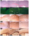
Tissue reactivity of PTFOS compared to Gelfilm® and a conventional grid. H&E panel shows greater tissue disruption (arrow) from the standard grid as compared to Gelfilm® or PTFOS. Fluoro-Jade panel shows bright lines of injured cells in the cortex (arrow) in contact with the standard grid as well as patches of injured cells in subcortical tissues (arrowheads). White dots indicate the interface between the implant and the cortical surface. Minimal injury is seen in the images of the tissues in contact with Gelfilm® and PTFOS. NeuN panel shows lower density of neuronal nuclei in the cortex in contact with the conventional grid as compared to Gelfilm® and PTFOS (compare the density of nuclei inside the frames). IBA-1 panel shows higher density of microglia in the cortex in contact with the conventional grid as compared to Gelfilm® and PTFOS (the arrow shows an area of microglia accumulation). Silver panel shows more disruption of cortical nerve fibers (arrow) from the conventional grid as compared to Gelfilm® or PTFOS. The images of the tissue neighboring PTFOS and Gelfilm® appear the same across all staining methods. This figure was previously reported in Radiology [2].
Figure 15
Figure 15
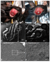
Microstructural stability of PTFOS implants. We implanted 5mm disks of PTFOS over the cortex of two mice (A). After 30 days, we harvested the PTFOS implant (B) and imaged it using a scanning electron microscope (C). For comparison, we also imaged a PTFOS disk that was not implanted (D). We used high-magnification levels, enabling us to see the PTFOS microstructure with the scale of 10 μm (E,F), to search selected areas of electrodes (arrows) and conductive lines (arrowheads) for the presence of breaks/cracks. We did not find any breaks/cracks in the electrodes/conductive lines of the PTFOS implants that were and were not implanted. This figure was previously reported in Radiology [2].

References

    1. Bonmassar G., Hadjikhani N., Ives J.R., Hinton D., Belliveau J.W. Influence of EEG electrodes on the BOLD fMRI signal. Hum. Brain Mapp. 2001;14:108–115. doi: 10.1002/hbm.1045. - DOI - PMC - PubMed
    1. Ahmadi E., Katnani H.A., Besheli L.D., Gu Q., Atefi R., Villeneuve M.Y., Eskandar E., Lev M.H., Golby A.J., Gupta R., et al. An Electrocorticography Grid with Conductive Nanoparticles in a Polymer Thick Film on an Organic Substrate Improves CT and MR Imaging. Radiology. 2016;280:595–601. doi: 10.1148/radiol.2016142529. - DOI - PMC - PubMed
    1. Levitt J., van der Kouwe A., Jeong H., Lewis L.D., Bonmassar G. The MotoNet: A 3 Tesla MRI-Conditional EEG Net with Embedded Motion Sensors. Sensors. 2023;23:3539. doi: 10.3390/s23073539. - DOI - PMC - PubMed
    1. Poulsen C., Wakeman D.G., Atefi S.R., Luu P., Konyn A., Bonmassar G. Polymer thick film technology for improved simultaneous dEEG/MRI recording: Safety and MRI data quality. Magn. Reson. Med. 2017;77:895–903. doi: 10.1002/mrm.26116. - DOI - PMC - PubMed
    1. Vasios C.E., Angelone L.M., Purdon P.L., Ahveninen J., Belliveau J.W., Bonmassar G. EEG/(f)MRI measurements at 7 Tesla using a new EEG cap (“InkCap”) Neuroimage. 2006;33:1082–1092. doi: 10.1016/j.neuroimage.2006.07.038. - DOI - PubMed

LinkOut - more resources