. 2024 Aug 16;24(16):5319.
doi: 10.3390/s24165319.

Differential Signal-Amplitude-Modulated Multi-Beam Remote Optical Touch Based on Grating Antenna

Affiliations

Differential Signal-Amplitude-Modulated Multi-Beam Remote Optical Touch Based on Grating Antenna

Yanwen Huang et al. Sensors (Basel). .

Abstract

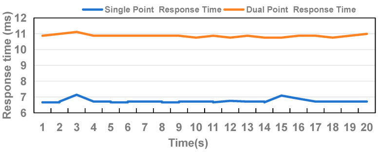
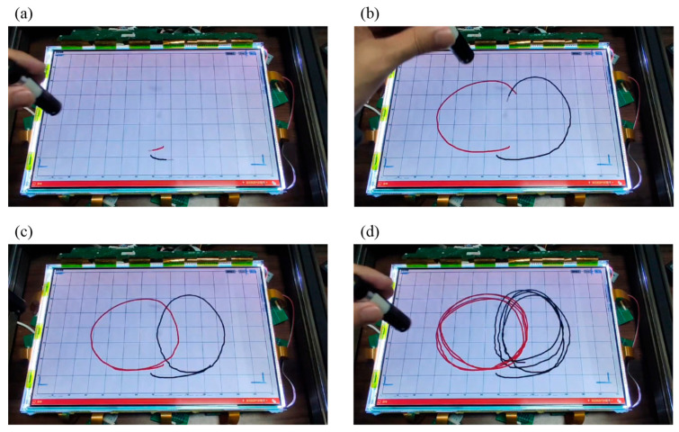
As screen sizes are becoming larger and larger, exceeding human physical limitations for direct interaction via touching, remote control is inevitable. However, among the current solutions, inertial gyroscopes are susceptible to positional inaccuracies, and gesture recognition is limited by cameras' focus depths and viewing angles. Provided that the issue of ghost points can be effectively addressed, grating antenna light-trapping technology is an ideal candidate for multipoint inputs. Therefore, we propose a differential amplitude modulation scheme for grating antenna-based multi-beam optical touch, which can recognize different incidence points. The amplitude of the incident beams was first coded with different pulse widths. Then, following the capture of incident beams by the grating antenna and their conversion into electrical currents by the aligned detector arrays, the incident points of the individual beams were recognized and differentiated. The scheme was successfully verified on an 18-inch screen, where two-point optical touch with a position accuracy error of under 3 mm and a response time of less than 7 ms under a modulation frequency of 10 kHz on both incident beams was achieved. This work demonstrates a practical method to achieve remote multi-point touch, which can make digital mice more accurately represent the users' pointing directions by obeying the natural three-point one-line aiming rule instantaneously.

Keywords: differential amplitude modulation; grating antenna; optical interaction; remote multi-touch.


Conflict of interest statement

The authors declare no conflicts of interest.

Figures

Figure 1
Figure 1
Schematic diagram of the multi-point optical interaction system. Pulse signals with different widths are modulated onto the infrared lasers.
Figure 2
Figure 2
Diagram of light transmission in the grating antenna layer. The incident light from the free space is coupled with the grating antenna, and then converted into the confined light propagating along the waveguide. Finally, it is captured by the photodetectors positioned around the screens.
Figure 3
Figure 3
(a) Schematic diagram of the grating antenna and waveguide. (b) +1 order diffraction efficiencies of the grating antenna with incident wavelengths ranging from 350 nm to 1200 nm and grating periods of 600–1000 nm. (c) +1 order diffraction efficiencies of the grating with grating heights ranging from 0 nm to 500 nm and a grating period of 650 nm. (d) +1 order diffraction grating efficiencies with duty cycles ranging from 0.1 to 0.9 and a grating period of 650 nm.
Figure 4
Figure 4
The diagram of hardware components and layout of the optical touch system. It includes an LCD panel, two layer of optical waveguide films, a backlight module, detector arrays, an electronic signal circuit, and a microcontroller unit.
Figure 5
Figure 5
(a) The set-up of a detector unit consisting of a phototransistor, a Schottky diode, and a sampling resistor. (b) The working process of how the grating antenna-based position recognition module obtains the incident light positions and displays them on the screen, including the signal scanning of detector arrays, ambient light calibration, peak voltage position calculation, modulated signal feature identification, and interaction points display.
Figure 6
Figure 6
The diagram of how the signals are transmitted in the optical touch system. The periodic fluctuations in the laser amplitude, linked to the PWM signals, are transformed into digital voltage signals by sampling the detection circuit. Then, the digital voltage signals are converted into Boolean values through dynamic threshold judgments and classified by the rising and falling edges to demodulate the pulse’s width and frequency characteristics.
Figure 7
Figure 7
Distortion analysis of signal demodulation. The sum effect of the prolonged rising and falling times can result in pulse stretching or compression, leading to signal distortion.
Figure 8
Figure 8
The experimental setup of the optical touch system, consisting of three movable rails, a laser pointer, a display screen, and a detector array. The laser pointer fixed on one of the Y-directional rails could scan the entire screen by moving the X or Y rails.
Figure 9
Figure 9
The diagram of the single-input experiments. (a) A 9-point measurement schematic to evaluate the position detection accuracy. (b) The response values of the sensor array when the laser pointer is illuminated to the position of No. 5. (c) Error evaluation of single input experiment.
Figure 10
Figure 10
Two-point touch error measurements, including (a1) the same Y, (a2) the same X, and (a3) different X and Y coordinates. (b) The response values of the sensor arrays when the laser pointer is illuminated, as shown in (a1). (c) Error evaluation of dual input experiment.
Figure 11
Figure 11
Comparative analysis of DCD method in single-point and dual-point scenarios with response time.
Figure 12
Figure 12
Demonstration of simultaneous dual-point writing. Two laser pointers were utilized to draw intersecting circles on the screen, with the display reflecting the recognition outcomes. The process is divided into four stages of (a) starting, (b) intersecting, (c) returning, and (d) repeating.

Similar articles

References

    1. Ren X., Silpasuwanchai C., Cahill J. Human-engaged computing: The future of human–computer interaction. CCF Trans. Pervasive Comput. Interact. 2019;1:47–68. doi: 10.1007/s42486-019-00007-0. - DOI
    1. Kotian A.L., Nandipi R., Ushag M., Veena G. A Systematic Review on Human and Computer Interaction; Proceedings of the 2024 2nd International Conference on Intelligent Data Communication Technologies and Internet of Things (IDCIoT); Bengaluru, India. 4–6 January 2024; pp. 1214–1218.
    1. Barrett G., Omote R. Projected-capacitive touch technology. Inf. Disp. 2010;26:16–21. doi: 10.1002/j.2637-496X.2010.tb00229.x. - DOI
    1. Calpe-Maravilla J., Medina I., Martinez M.J., Carbajo A. Dual touch and gesture recognition in 4-wire resistive touchscreens; Proceedings of the SENSORS, 2014 IEEE; Valencia, Spain. 2–5 November 2014; pp. 787–790.
    1. Mandal D., Banerjee S. Surface acoustic wave (SAW) sensors: Physics, materials, and applications. Sensors. 2022;22:820. doi: 10.3390/s22030820. - DOI - PMC - PubMed

LinkOut - more resources