. 2024 Sep 3;16(1):279.
doi: 10.1007/s40820-024-01502-5.

3D Printing of Periodic Porous Metamaterials for Tunable Electromagnetic Shielding Across Broad Frequencies

Affiliations

3D Printing of Periodic Porous Metamaterials for Tunable Electromagnetic Shielding Across Broad Frequencies

Qinniu Lv et al. Nanomicro Lett. .

Abstract

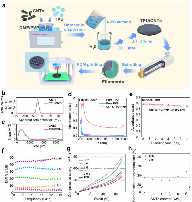
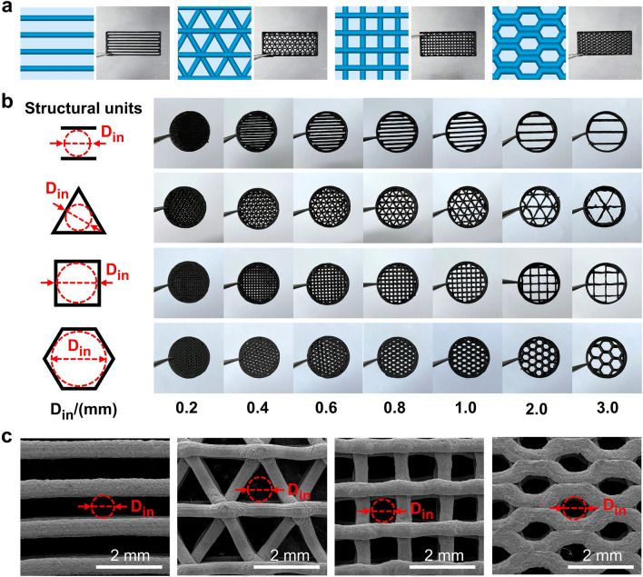
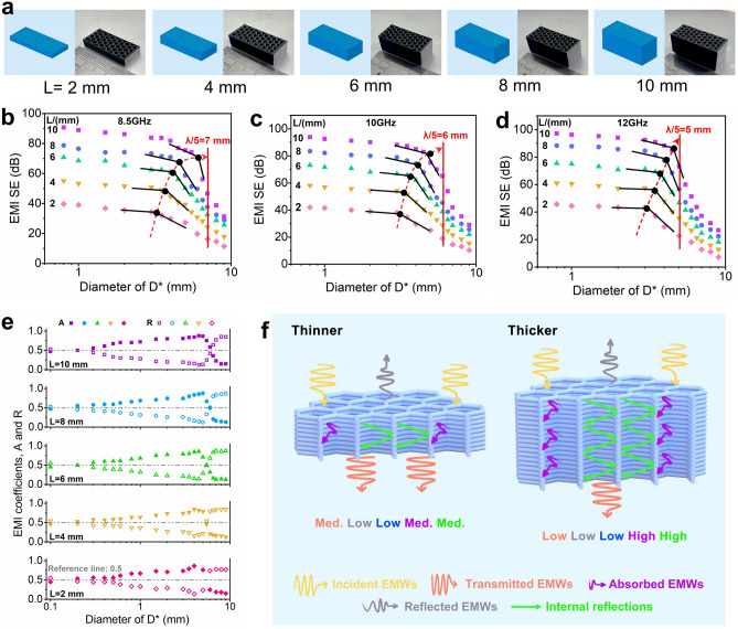
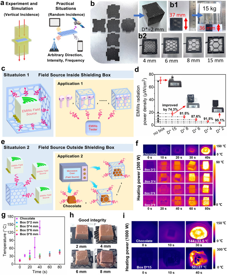
The new-generation electronic components require a balance between electromagnetic interference shielding efficiency and open structure factors such as ventilation and heat dissipation. In addition, realizing the tunable shielding of porous shields over a wide range of wavelengths is even more challenging. In this study, the well-prepared thermoplastic polyurethane/carbon nanotubes composites were used to fabricate the novel periodic porous flexible metamaterials using fused deposition modeling 3D printing. Particularly, the investigation focuses on optimization of pore geometry, size, dislocation configuration and material thickness, thus establishing a clear correlation between structural parameters and shielding property. Both experimental and simulation results have validated the superior shielding performance of hexagon derived honeycomb structure over other designs, and proposed the failure shielding size (Df ≈λ/8 - λ/5) and critical inclined angle (θf ≈43° - 48°), which could be used as new benchmarks for tunable electromagnetic shielding. In addition, the proper regulation of the material thickness could remarkably enhance the maximum shielding capability (85 - 95 dB) and absorption coefficient A (over 0.83). The final innovative design of the porous shielding box also exhibits good shielding effectiveness across a broad frequency range (over 2.4 GHz), opening up novel pathways for individualized and diversified shielding solutions.

Keywords: 3D printing; Honeycomb pore structure; Periodic porous metamaterials; Polymeric component; Tunable electromagnetic shielding.


Conflict of interest statement

The authors declare no conflict of interest. They have no known competing financial interests or personal relationships that could have appeared to influence the work reported in this paper.

Figures

Fig. 1
Fig. 1
a Schematic diagram for preparation of TPU/CNTs printing filaments and the 3D printing process. The characterization of CNTs and TPU/CNTs suspension, including b Zeta potential, c particle size distribution and d UV–Vis-NIR spectrum; e CNTs stability characterization by using UV–Vis-NIR spectrum at 500 nm wavelength; f EMI SE of TPU/CNTs composite filament, g compressive strength versus strain curves and h the compression deformation rate of L-n composites with different CNTs content
Fig. 2
Fig. 2
a FDM printing models and the optical images of printed parts (dimensions of 22.9 × 10.2 × 2.0 mm3) with different periodic pore units; b Optimal images of the printed different periodic pore structure units (assembled in circular porous part with diameter 12 mm and thickness 2 mm) with different inscribed circle diameter (Din); c SEM images of 0.8 mm Din size samples with different pore units
Fig. 3
Fig. 3
EMI SE of printed samples with various pore structure unit at different Din including a straight, b triangle, c square and d honeycomb; e EMI SE versus pore factor c of corresponding printed samples; the simulation results of f electric-field distribution and g power loss density of 2 mm Din sample with different pore structure unit; h schematic representation of the corresponding shielding mechanism
Fig. 4
Fig. 4
a Optical images of honeycomb sample, b schematic comparison of parameters Din, Dout and D*. c Optical images of honeycomb structural units with different D* dimensions. d Average electromagnetic parameters (SET, SEA, and SER), e absorption coefficient A, reflection coefficient R (at L = 2 mm thickness) and f overall EMI SE effectiveness in the X-band for printed samples of different D* sizes. g EMI SE at 8.5, 10, 12, and 15 GHz for printed honeycomb samples with different size of D* and h schematic representation of the corresponding shielding mechanism
Fig. 5
Fig. 5
a FDM printing models, optical images of printed samples with different thickness. The EMI SE at b 8.5, c 10, d 12 GHz and the e absorption coefficient A and reflection coefficient R of printed samples with different thickness. f Schematic representation of the corresponding shielding mechanism
Fig. 6
Fig. 6
a Optical image of the misaligned structure and a schematic diagram of its front view cross section (YZ plane); b top view (XY plane) of the FDM printing models and optical images; c SET and d SER of printed samples with different misaligned structure; e schematic diagrams and values of different inclined angles θ; f SET and g SER of printed samples with different inclined angles θ; h schematic representation of the corresponding shielding mechanism
Fig. 7
Fig. 7
a Schematic diagram for various transmission form of electromagnetic waves in different scenarios; b–b2 digital photographs of the printed shielding boxes with different D* size and the compression test with a 15 kg load done on a D* = 2 mm shielding box; c schematic diagram for placing earphone as EMWs field source inside the printed shielding box and d EMWs radiation intensity value received outside; e schematic diagram of using a microwave oven (300 W working power) as EMWs field source for microwave treatment of a printed shielding box with chocolate filled in, f the corresponding thermal imaging picture, g the extracted specific temperature values and h the digital photographs of the filled chocolate with microwave treatment; i the thermal imaging pictures of the naked chocolate and the filled chocolate in the printed D* = 15 mm shielding box under irradiation of microwave oven with 1000 W power

References

    1. A. Iqbal, P. Sambyal, C. Koo, Electromagnetic interference shielding: 2D MXenes for electromagnetic shielding: A review. Adv. Funct. Mater. 30, 2070307 (2020). 10.1002/adfm.202070307
    1. F. Shahzad, M. Alhabeb, C. Hatter, B. Anasori, S. Man Hong et al., Electromagnetic interference shielding with 2D transition metal carbides (MXenes). Science 353, 1137–1140 (2016). 10.1126/science.aag2421 - PubMed
    1. Q. Wei, S. Pei, X. Qian, H. Liu, Z. Liu et al., Superhigh electromagnetic interference shielding of ultrathin aligned pristine graphene nanosheets film. Adv. Mater. 32, 1907411 (2020). 10.1002/adma.201907411 - PubMed
    1. S.K. Srivastava, K. Manna, Recent advancements in the electromagnetic interference shielding performance of nanostructured materials and their nanocomposites: A review. J. Mater. Chem. A 10, 7431–7496 (2022). 10.1039/d1ta09522f
    1. B. Wei, L. Zhang, S. Yang, Polymer composites with expanded graphite network with superior thermal conductivity and electromagnetic interference shielding performance. Chem. Eng. J. 404, 126437 (2021). 10.1016/j.cej.2020.126437

LinkOut - more resources