

Design and Control of an Upper Limb Bionic Exoskeleton Rehabilitation Device Based on Tensegrity Structure
- PMID: 39239384
- PMCID: PMC11377110
- DOI: 10.1155/2024/5905225
Design and Control of an Upper Limb Bionic Exoskeleton Rehabilitation Device Based on Tensegrity Structure
Abstract
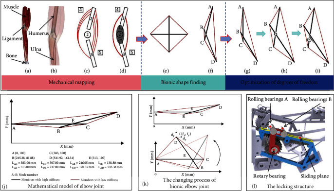
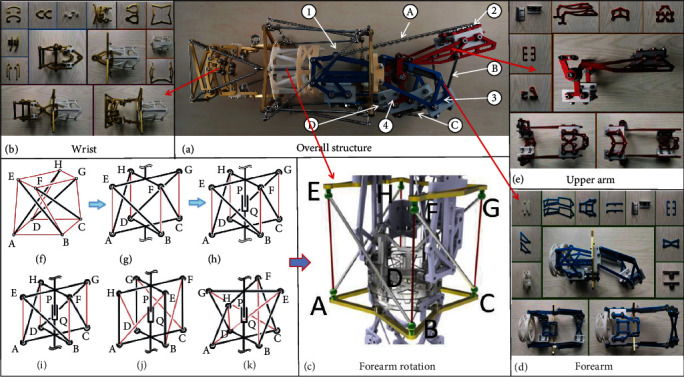
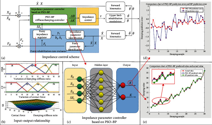
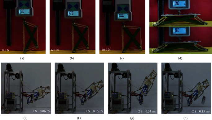
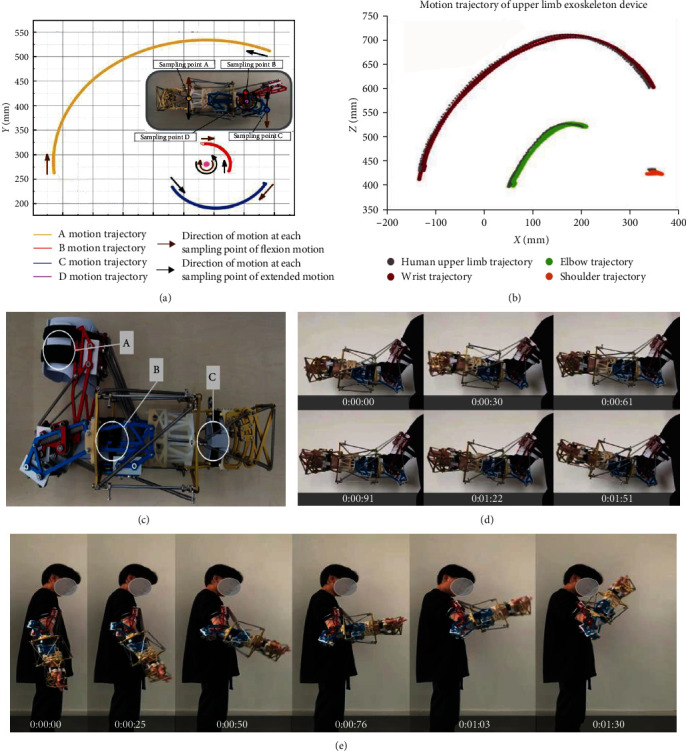
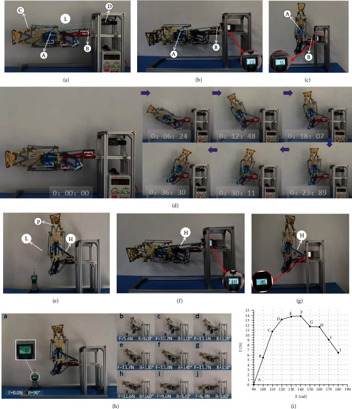
Upper limb exoskeleton rehabilitation devices can improve the quality of rehabilitation and relieve the pressure of rehabilitation medical treatment, which is a research hotspot in the field of medical robots. Aiming at the problems such as large volume, high cost, low comfort, and difficulty in promotion of traditional exoskeleton rehabilitation devices, and considering the lightweight, discontinuous, high flexibility, and high biomimetic characteristics of tensegrity structure, we designed an upper limb bionic exoskeleton rehabilitation device based on tensegrity structure. First, this article uses mapping methods to establish a mapping model for upper limb exoskeletons based on the tensegrity structure and designs the overall structure of upper limb exoskeletons based on the mapping model. Second, a bionic elbow joint device based on gear and rack was designed, and the stability of the bionic elbow joint was proved using the positive definite matrix method. This device can simulate the micro displacement between bones of the human elbow joint, improve the axial matching ability between the upper limbs and the rehabilitation device, and enhance the comfort of rehabilitation. Third, an impedance control scheme based on back propagation (BP) neural network was designed to address the low control accuracy of flexible structures and patient spasms. Finally, we designed the impedance control scheme of the PSO-BP neural network based on a fuzzy rehabilitation state evaluator. The experimental results show that the exoskeleton rehabilitation device has good flexion motion stability and assist ability and has significant advantages in volume and mobility. The control strategy proposed in this paper has high control precision and adaptive ability and has potential application value in the field of medical rehabilitation.
Copyright © 2024 Peng Ni et al.
Conflict of interest statement
The authors declare that they have no conflicts of interest.
Figures
References
-
- Manna S. K., Bhaumik S. A bioinspired 10 DOF wearable powered arm exoskeleton for rehabilitation. Journal of Robotics . 2013;2013:15. doi: 10.1155/2013/741359.741359 - DOI
-
- Huang J., Tu X., He J. Design and evaluation of the RUPERT wearable upper extremity exoskeleton robot for clinical and in-home therapies. IEEE Transactions on Systems, Man, and Cybernetics: Systems . 2016;46(7):926–935. doi: 10.1109/TSMC.2015.2497205. - DOI
LinkOut - more resources
Full Text Sources
