. 2024 Sep 6;15(1):7800.
doi: 10.1038/s41467-024-51987-2.

Wearable bio-adhesive metal detector array (BioMDA) for spinal implants

Affiliations

Wearable bio-adhesive metal detector array (BioMDA) for spinal implants

Jian Li et al. Nat Commun. .

Abstract

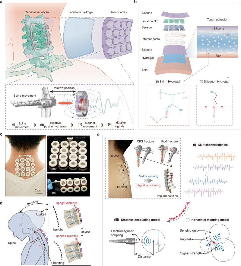
Dynamic tracking of spinal instrumentation could facilitate real-time evaluation of hardware integrity and in so doing alert patients/clinicians of potential failure(s). Critically, no method yet exists to continually monitor the integrity of spinal hardware and by proxy the process of spinal arthrodesis; as such hardware failures are often not appreciated until clinical symptoms manifest. Accordingly, herein, we report on the development and engineering of a bio-adhesive metal detector array (BioMDA), a potential wearable solution for real-time, non-invasive positional analyses of osseous implants within the spine. The electromagnetic coupling mechanism and intimate interfacial adhesion enable the precise sensing of the metallic implants position without the use of radiation. The customized decoupling models developed facilitate the precise determination of the horizontal and vertical positions of the implants with incredible levels of accuracy (e.g., <0.5 mm). These data support the potential use of BioMDA in real-time/dynamic postoperative monitoring of spinal implants.


Conflict of interest statement

J.D.B. has an equity position in Treovir Inc. and UpFront Diagnostics. J.D.B. is also a co-founder of Centile Bioscience and on the NeuroX1 scientific advisory board. The authors declare filing of a provisional patent application encompassing the work described.

Figures

Fig. 1
Fig. 1. Design and working principles of the bio-adhesive metal implant detector array (BioMDA).
a Schematic illustration of the working principle of the BioMDA. The sensor array is mounted to the skin above the cervical vertebrae, allowing for relative position changes during a set of neck movements. b Layered schematic illustration of the components of the BioMDA and the robust covalent connection achieved through the bio-adhesive with both silicone encapsulation and the skin. c Optical images showing the BioMDA mounted on user’s neck (left) as well as its remarkable flexibility (right). d Schematic illustration showing how relative position change between the BioMDA and cervical implants are achieved via a set of bending movements. e Workflow diagram showing the BioMDA in diagnosing cervical pedicle screws (CPS) fracture or rod fracture through determining position changes of implants, where multichannel sensing signals arising from BioMDA are transmitted to the horizontal mapping model and the distance decoupling model sequentially for real-time 3D localization.
Fig. 2
Fig. 2. Structural parameters optimization and characterization of the single sensing unit.
a Schematic illustration of the components comprising a single sensing unit. PET stands for polyethylene terephthalate. b Force state analysis of the permanent magnet in response to external attractive force and structural parameters that determine the sensing capability and stability of the unit. Schematic illustration of the platform (c) utilized to study the force changes with increased deviating distance (d) with nickel coating thickness ranging from 0 to 200 nm. e Finite element analysis results showing the strain distribution of the supporting PET film with thickness of 50 µm and 250 µm in response to the external attractive force of 100 mN. Measured response signal amplitude (f) and maximum detection distance (g) variation with a set of film thicknesses ranging from 50 µm to 250 µm. h Measured response signal amplitude with central angle of the PET film ranging from 30° to 90°, bar height, mean; error bars, s.d.; n = 3 independent tests. i Measured response signal showing the cyclic variation during implant approaching, holding, and deviating process. j Fast Fourier Transform (FFT) of the response signal in (i) showing the movement frequency of the implant. k Response signals in over 4000 approaching and deviating cycles showing the stability of the single sensing unit.
Fig. 3
Fig. 3. Interfacial robustness and electrical performance evaluation.
a Schematic illustration of the interfacial bonding achieved by the bio-adhesive with both the skin and the silicone encapsulation. PAA stands for poly (acrylic acid). Formation of the covalent connection between bio-adhesive and the skin (b) as well as the bio-adhesive and the amino grafted silicone elastomer (c). d Schematics and force variation to increased separation distance results showing the interface toughness between skin-skin and skin- polydimethylsiloxane (PDMS) connection during 180° peel test. Inset scale bars: 1 cm. e Schematics and shear stress variation with increased separation distance during shear test. Inset scale bars: 1 cm. f Optical images showing the settings of the BioMDA and metal screws in electrical performance validation experiments. Scale bars: 1 cm. Response signals from the 4 highlighted channels at bending cycle 1 (g) and bending cycle 100 (h) and Signal-to-noise ratio (SNR) comparison (i) with bio-adhesive as interface material. Response signals from the 4 highlighted channels at bending cycle 1 (j) and bending cycle 100 (k) and SNR comparison (l) with commercial adhesive as interface material. Center line, median; box limits, upper and lower quartiles; whiskers, 1.5 × interquartile range; n = 4 independent signals in Figs. i and l.
Fig. 4
Fig. 4. Decoupling models construction and performance evaluation.
a Framework of the electromagnetic-kinematic decoupling model to calculate the vertical distance of the implants related to BioMDA. This model calculates the vertical distance z between implants and sensors by decoupling the electromagnetic and kinematic interactions, with F representing the force exerted. b Visualization of the difference between the theoretical model without and with the calibrated attenuation model. The calibration approximates the scaling between theoretical model ε0(zi) to the captured inducing signal across the coil ε(zm) and can be divided into two steps scaling in the distance space (c) and velocity space (d). e The comparison between the calibrated model ε^zm and test samples is visualized for distances ranging from 1.25 to 6.5 mm and velocities ranging from 7 to 15.5 mm/sec. Optical images of screw malposition (f) and screw immigration (j) with spinal cord. g, k Decoupled spatial distribution of the implants. To estimate the vertical distance of the implants, the electromagnetic-kinematic model is sliced by the maximum amplitude of the captured inducing signal (h, l), where red lines indicate abnormal signal from malfunctioned implants and blue lines for normal implants. The localization results include an estimated range of distance (i, m). Scale bars in f and j: 1 cm.

Similar articles

Cited by

References

    1. Reid, P. C., Morr, S. & Kaiser, M. G. State of the union: a review of lumbar fusion indications and techniques for degenerative spine disease: JNSPG 75th Anniversary Invited Review Article. J. Neurosurg. Spine31, 1–14 (2019). 10.3171/2019.4.SPINE18915 - DOI - PubMed
    1. Slone, R. M., MacMillan, M. & Montgomery, W. J. Spinal fixation. Part 1. Principles, basic hardware, and fixation techniques for the cervical spine. RadioGraphics13, 341–356 (1993). 10.1148/radiographics.13.2.8460224 - DOI - PubMed
    1. Slone, R. M., MacMillan, M., Montgomery, W. J. & Heare, M. Spinal fixation. Part 2. Fixation techniques and hardware for the thoracic and lumbosacral spine. RadioGraphics13, 521–543 (1993). 10.1148/radiographics.13.3.8316661 - DOI - PubMed
    1. Fujimoto, T. et al. Pedicle screw diameter selection for safe insertion in the thoracic spine. Eur. J. Orthop. Surg. Traumatol.22, 351–356 (2012).10.1007/s00590-011-0846-2 - DOI
    1. Rong, X., Lou, J., Li, H., Meng, Y. & Liu, H. How to choose when implants of adjacent height both fit the disc space properly in single-level cervical artificial disc replacement. Med. (Baltim.)96, e6954 (2017).10.1097/MD.0000000000006954 - DOI - PMC - PubMed

Publication types

LinkOut - more resources