Review
. 2024 Sep 9;17(17):1963-1979.
doi: 10.1016/j.jcin.2024.07.007.

Emerging Hybrid Intracoronary Imaging Technologies and Their Applications in Clinical Practice and Research

Affiliations
Review

Emerging Hybrid Intracoronary Imaging Technologies and Their Applications in Clinical Practice and Research

Vincenzo Tufaro et al. JACC Cardiovasc Interv. .

Abstract

Intravascular ultrasound and optical coherence tomography are used with increasing frequency for the care of coronary patients and in research studies. These imaging tools can identify culprit lesions in acute coronary syndromes, assess coronary stenosis severity, guide percutaneous coronary intervention (PCI), and detect vulnerable plaques and patients. However, they have significant limitations that have stimulated the development of multimodality intracoronary imaging catheters, which provide improvements in assessing vessel wall pathology and guiding PCI. Prototypes combining 2 or even 3 imaging probes with complementary attributes have been developed, and several multimodality systems have already been used in patients, with near-infrared spectroscopy intravascular ultrasound-based studies showing promising results for the identification of high-risk plaques. Moreover, postmortem histology studies have documented that hybrid imaging catheters can enable more accurate characterization of plaque morphology than standalone imaging. This review describes the evolution in the field of hybrid intracoronary imaging; presents the available multimodality catheters; and discusses their potential role in PCI guidance, vulnerable plaque detection, and the assessment of endovascular devices and emerging pharmacotherapies targeting atherosclerosis.

Keywords: hybrid intravascular imaging; intravascular ultrasound; near-infrared fluorescence; near-infrared spectroscopy; optical coherence tomography.


Conflict of interest statement

Funding Support and Author Disclosures Prof Jaffer has received research grants from Canon, Siemens, Shockwave, Teleflex, Mercator, Boston Scientific, HeartFlow, and Neovasc; has received consultant/speaker fees from Boston Scientific, Siemens, Magenta Medical, Philips, Biotronik, Mercator, and Abiomed; has equity interest in Intravascular Imaging Inc and DurVena. Massachusetts General Hospital has licensing arrangements with Terumo, Canon, and SpectraWAVE; Dr Jaffer has the right to receive royalties. Prof Serruys has served as a consultant for Merillife, Novartis, Xeltis, SMT, and Philips. Prof Stone has received speaker honoraria from Medtronic, Pulnovo, Infraredx, Abiomed, Amgen, and Boehringer Ingelheim; has served as a consultant for Abbott, Daiichi-Sankyo, Ablative Solutions, CorFlow, Apollo Therapeutics, Cardiomech, Gore, Robocath, Miracor, Vectorious, Abiomed, Valfix, TherOx, HeartFlow, Neovasc, Ancora, Elucid Bio, Occlutech, Impulse Dynamics, Adona Medical, Millennia Biopharma, Oxitope, Cardiac Success, and HighLife; and has equity/options from Ancora, Cagent, Applied Therapeutics, Biostar family of funds, SpectraWAVE, Orchestra Biomed, Aria, Cardiac Success, Valfix, and Xenter. Prof Stone’s employer, Mount Sinai Hospital, receives research grants from Abbott, Abiomed, Bioventrix, Cardiovascular Systems Inc, Phillips, Biosense-Webster, Shockwave, Vascular Dynamics, Pulnovo, and V-wave. Prof Muller is a cofounder of, has equity interest in, has served as a consultant for, and is not an employee of SpectraWAVE; and is a cofounder with no financial interest in Infraredx, Inc. Prof Van Soest is a cofounder of, consultant for, and has financial interest in Kaminari Medical BV, which develops IVPA/IVUS technology; and has received research grants from Boston Scientific. Dr Courtney is an employee of; has shareholder/equity interest in Conavi Medical Inc; and has received stock options, royalties, and research funding from Conavi Medical Inc. Prof Tearney has financial/fiduciary interest in SpectraWave, a company developing an OCT NIRS intracoronary imaging system and catheter. His financial/fiduciary interest was reviewed and is managed by Massachusetts General Brigham in accordance with their conflict of interest policies. Prof Tearney has received materials from Terumo Corporation; and has received sponsored research funding from Canon Medical. All other authors have reported that they have no relationships relevant to the contents of this paper to disclose.

Figures
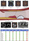
FIGURE 1
FIGURE 1. Performance of Standalone and Hybrid Intravascular Imaging in Detecting the Most Common Causes of Stent Failure
The table displays a quantification of the efficacy of each modality in detecting different intrastent and stent edge features that have been proven in intravascular imaging studies to be associated with adverse events. The red circle indicates that the modality is unable to detect the specific feature. Conversely, a one-quarter, one-half, three-quarters, or a full green circle indicate weak, moderate, good, or excellent ability to detect that feature, respectively. Image of OCT-NIRF showing uncovered struts adapted with permission from https://doi.org/10.1093/eurheartj/ehv677. FLIm-IVUS = fluorescence lifetime imaging intravascular ultrasound; FLIm-OCT = fluorescence lifetime imaging optical coherence tomography; IVPA-IVUS = intravascular photoacoustic intravascular ultrasound; IVUS = intravascular ultrasound; IVUS-OCT = intravascular ultrasound optical coherence tomography; NIRF-IVUS = near-infrared fluorescence intravascular ultrasound; NIRS-IVUS = near-infrared spectroscopy intravascular ultrasound; OCT = optical coherence tomography; OCT-NIRF = optical coherence tomography near-infrared fluorescence; OCT-NIRS = optical coherence tomography near-infrared spectroscopy.
FIGURE 2
FIGURE 2. Value of Combined IVUS OCT Imaging in Guiding Percutaneous Coronary Intervention
A and B show the efficacy of this approach in detecting the proximal and distal landing zone for stent implantation with IVUS allowing accurate plaque burden measurement and OCT permitting the detection of lipid tissue. C to H show the superiority of OCT over IVUS in identifying common causes of stent failure, in particular (D) stent edge dissection, (F) malapposition, and (H) thrombus protrusion that are visible by OCT but not by IVUS. Abbreviations as in Figure 1.
FIGURE 3
FIGURE 3. Advantages and Limitations of Standalone and Hybrid Intravascular Imaging in Assessing Calcific-Rich Plaques
IVUS (A) and OCT imaging (C) can detect the presence of calcific tissue, but they cannot identify the presence of lipid within the calcific tissue as shown in the corresponding hematoxylin-eosin histologic images in B and D. Conversely, combined NIRS-IVUS imaging can detect the lipid tissue within the calcium as shown in E and F. Similarly, intravascular photoacoustic imaging can identify lipid tissue distribution; in the example shown in G, the lipid is present at the edge of the calcific tissue but not within the calcium. This is confirmed by the corresponding histology section (H) stained with oil red O (ORO). Similarly, FLIM-IVUS can detect the presence of the superficial lipid in a calcific-rich plaque; in the example displayed in I, fluorescence lifetime imaging (FLIm) showed that no lipid tissue is present in the superficial 200 to 250 mm (within the FLIm penetration depth) of a calcified lesion. This is also demonstrated in the (J) corresponding histology section stained with Movats pentachrome. Finally, K demonstrates OCT NIRF with indocyanine green (ICG) plaque uptake (red arrowhead) in a lesion with intimal and medial calcification (yellow arrowheads) confirmed by IVUS in L; in addition, M illustrates a fluorescence microscopy image showing increased ICG uptake suggesting the presence of lipid tissue. Abbreviations as in Figure 1.
FIGURE 4
FIGURE 4. Efficacy of OCT-NIRF Imaging in Detecting Fibrin Deposition on Stents
Rabbits underwent implantation of a bare-metal stent (BMS) and a drug-eluting stent (DES) in the aorta. At day 7, the FTP11-CyAm7 agent was injected that binds fibrin, and then OCT-NIRF imaging was performed. A shows OCT-NIRF maps, the corresponding ex vivo longitudinal imaging, and the florescence microscopy image. Cross-sectional OCT-NIRF frames at the (ii) center and (i and iii) edge of the stent are shown in B, whereas C and D portray florescence microscopy and histology images stained with Carstairs stain at the proximal stent edge (dotted line in A [i]). The NIRF signal of FTP11-CyAm7 (red) colocalized with fibrin indicated with a bright red color in Carstairs staining and fibrin immunostaining. Finally, E shows OCT-NIRF cross-sectional images obtained in a BMS and DES 7 days poststent deployment. In these frames, the struts are covered either by endothelium (white arrows) or fibrin (yellow arrows). OCT signal intensity is similar because OCT cannot differentiate fibrin from the endothelium. The corresponding fibrin immunostaining and endothelial nitric oxide synthase immunostaining (magnified images) are shown below the OCT-NIRF images. It is apparent that in contrast to BMS, in the DES there is increased fibrin deposition and limited endothelial nitric oxide synthase (eNOS) expression. Images adapted with permission from https://doi.org/10.1093/eurheartj/ehv677. 2D = 2-dimensional; FITC = fluorescein isothiocyanate; FM = fluorescence microscopy; FTPII = fibrin-targeted peptide; NIRF = near-infrared fluorescence; OCT NIRF = near-infrared fluorescence optical coherence tomography.
FIGURE 5
FIGURE 5. Efficacy of NIRF Imaging in Detecting Vascular Inflammation and Protease Activity in BMS and EES Implanted in the Abdominal Aorta of a Rabbit
A shows an angiographic projection of the implanted stents in the aorta. The white lines indicate the location of the 2 stents, whereas P1 and P2 are the location of 2 plaques identified by IVUS. B portrays a 2D image with the NIRF obtained in vivo by a NIRF catheter 4 weeks after stent implantation and after administration of the cysteine proteaseactivatable NIRF imaging agent Prosense VM110, with the y-axis representing the angular (0–360) and the x-axis the longitudinal dimensions (mm). The asterisk in this image indicates the guidewire artifact. C portrays the NIRF signal along the longitudinal axis, and D shows a fusion image of the IVUS and intravascular NIRF data. E portrays an ex vivo fluorescence-reflected image at 800 nm of the resected aorta. In this set of images, the scale bar was set at 10 mm. F and G portray histologic cross sections obtained 4 weeks postBMS and EES stent implantation, respectively, immunostained with antibodies for the macrophage marker RAM-11 and protease cathepsin B; it is apparent that there is an increased inflammatory activity in the BMS but not in the EES. Images adapted with permission from https://doi.org/10.1093/ehjci/jew228. A.U. = arbitrary unit(s); EES = everolimus-eluting stent(s); other abbreviations as in Figures 1 and 4.
CENTRAL ILLUSTRATION
CENTRAL ILLUSTRATION. Current and Evolving Intracoronary Imaging to Detect Vulnerable Plaque Features
The table displays the performance of each modality in detecting different plaque characteristics that are associated with increased vulnerability. The full red circle indicates that the modality is unable to detect the specific feature, whereas a one-quarter, one-half, three-quarters, or a full green circle indicate weak, moderate, good, or excellent ability to detect the plaque characteristic, respectively. Image of OCT-NIRF showing macrophages adapted with permission from https://doi.org/610.1093/eurheartj/ehv726; IVPA-IVUS showing neovascularization adapted with permission from https://doi.org/10.1016/j.pacs.2021.100262; and OCT-NIRF showing plaque erosion adapted with permission from https://doi.org/10.1016/j.jcmg.2016.01.034. FLIm-IVUS = fluorescence lifetime imaging intravascular ultrasound; FLIm-OCT = fluorescence lifetime imaging optical coherence tomography; IVPA-IVUS = intravascular photoacoustic intravascular ultrasound; IVUS = intravascular ultrasound; IVUS-OCT = intravascular ultrasound optical coherence tomography; NIRF-IVUS = near-infrared fluorescence intravascular ultrasound; NIRS-IVUS = near-infrared spectroscopy intravascular ultrasound; OCT = optical coherence tomography; OCT-NIRF = optical coherence tomography near-infrared fluorescence; OCT-NIRS = optical coherence tomography near-infrared spectroscopy.

References

    1. Bourantas CV, Tenekecioglu E, Radu M, Raber L, Serruys PW. State of the art: role of intravascular imaging in the evolution of percutaneous coronary intervention - a 30-year review. EuroIntervention. 2017;13:644.. - PubMed
    1. Holm NR, Andreasen LN, Neghabat O, et al. OCT or angiography guidance for PCI in complex bifurcation lesions. N Engl J Med 2023;389(16): 1477.. - PubMed
    1. Raber L, Mintz GS, Koskinas KC, et al. Clinical use of intracoronary imaging. Part 1: guidance and optimization of coronary interventions. An expert consensus document of the European Association of Percutaneous Cardiovascular Interventions. Eur Heart J 2018;39:3281.. - PubMed
    1. Stone GW, Christiansen EH, Ali ZA, et al. Intravascular imaging-guided coronary drug-eluting stent implantation: an updated network meta-analysis. Lancet. 2024;403:824.. - PubMed
    1. Ladwiniec A, Walsh SJ, Holm NR, et al. Intravascular ultrasound to guide left main stem intervention: a NOBLE trial substudy. EuroIntervention. 2020;16:201.. - PubMed

MeSH terms