. 2024:32:3625-3635.
doi: 10.1109/TNSRE.2024.3459801. Epub 2024 Sep 27.

Development and Evaluation of a Real-Time Phase-Triggered Stimulation Algorithm for the CorTec Brain Interchange

Development and Evaluation of a Real-Time Phase-Triggered Stimulation Algorithm for the CorTec Brain Interchange

Hanbin Cho et al. IEEE Trans Neural Syst Rehabil Eng. 2024.

Abstract

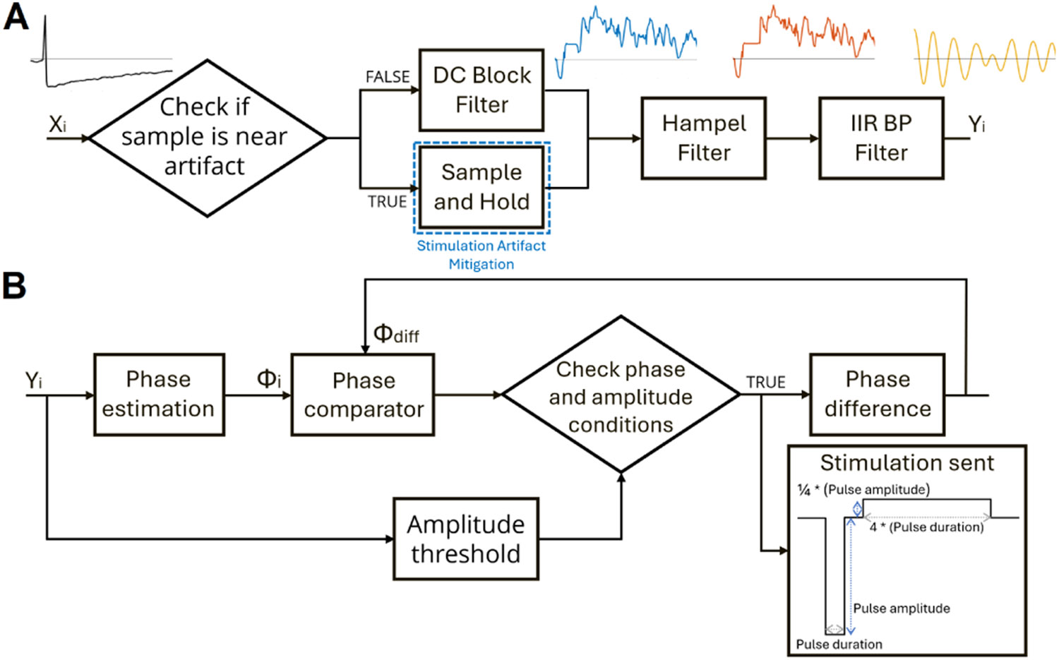
With the development and characterization of biomarkers that may reflect neural network state as well as a patient's clinical deficits, there is growing interest in more complex stimulation designs. While current implantable neuromodulation systems offer pathways to expand the design and application of adaptive stimulation paradigms, technological drawbacks of these systems limit adaptive neuromodulation exploration. In this paper, we discuss the implementation of a phase-triggered stimulation paradigm using a research platform composed of an investigational system known as the CorTec Brain Interchange (CorTec GmbH, Freiburg, Germany), and an open-source software tool known as OMNI-BIC. We then evaluate the stimulation paradigm's performance in both benchtop and in vivo human demonstrations. Our findings indicate that the Brain Interchange and OMNI-BIC platform is capable of reliable administration of phase-triggered stimulation and has the potential to help expand investigation within the adaptive neuromodulation design space.


Figures

Fig. 1.
Fig. 1.
Overview of the Brain Interchange (BIC) platform. Left: A system block diagram of the experimental setup with connections visualizing the exchange of information and signals between different components. Right: Benchtop development kit of the BIC research platform. A magnetic head piece (encircled) enables inductive power transmission, while wireless communication between A) the external BIC hardware and B) the emulated implant allows for neural data and stimulation command information to be streamed between the research computer and BIC device via USB. Proprietary API and OMNI-BIC software are installed on the research PC to enable interfacing between the BIC external hardware and the implant. For benchtop evaluation, the emulated implant connected to C) electrocorticography electrodes submerged in saline. The electrode configuration used for saline benchtop experiments included a contact for sensing activity to trigger stimulation (SSENSE), relative to another contact designated as the reference (SREF), and a pair of horizontally adjacent contacts for stimulation (SSTIM). For clinical evaluation, the emulated implant connected to D) percutaneous stereo-electroencephalography electrodes implanted in patients.
Fig. 2.
Fig. 2.
Components of the control algorithm incorporated within OMNI-BIC. A) Block diagram of the signal processing pipeline. Raw samples (Xi) streamed to the BIC device are sent through this pipeline to determine underlying filtered beta activity (Yi), sample by sample. Digital sample and holding was incorporated to mitigate stimulation artifact contamination. A segment of raw data with stimulation (black) and subsequent segments (blue, orange, and yellow) shows the outcomes of the segment after going through each signal processing component. B) Block diagram for the phase-locked loop phase-specific stimulation design. Amplitude and estimated phase (Φi) of an incoming filtered sample were used to determine if a stimulation command is sent. The difference in the target phase and estimated phase of stimulation (Φdiff) after delivery is used to adjust the triggering phase that determined the timing of stimulation.
Fig. 3.
Fig. 3.
Recordings from saline benchtop evaluation experiments. A) Time-synchronized data obtained from separate recording-only sessions capturing the same segment of electrophysiology playback into saline. Synchronicity between the two recordings establishes repeatability and consistency across multiple benchtop recordings. B) Time-synchronized filtered data obtained from both recording-only sessions (blue and orange) and a session of beta phase-triggered stimulation (yellow) with observed stimulation activity (purple). Filtered oscillations are obtained from the same segment of electrophysiology playback depicted in Fig. 3A. This segment of beta phase-triggered stimulation indicates a limitation of the predictive nature of the PLL design to accommodate for the system latency. Satisfaction of the amplitude and phase conditions assumes a valid incoming beta oscillation target. The shaded oscillation demonstrates a scenario where criteria were satisfied and a stimulation response was triggered, but it was not a proper target for stimulation. However, these additional stimulation pulses are not hazardous and occur occasionally throughout evaluations.
Fig. 4.
Fig. 4.
Outcomes from demonstrations of phase-triggered stimulation with the BIC device. Polar histograms of the phase angle at which stimulation occurred along the filtered beta signal during A) saline tank (ST1 and ST2), and B) clinical subject (CS1 and CS2) demonstrations. C) Time series plot of raw recorded signals in a benchtop experiment with observed stimulation artifact and playback of previously recorded electrophysiology (collected from CorTec BIC devices in ovine models) injected into the saline tank. D) Time series plot of filtered beta activity and stimulation timing synchronized with (C). Samples that satisfy the phase and amplitude conditions of the implemented phase-locked loop design are denoted in yellow and indicate when a stimulation command is initiated. E) Boxplots of latencies between initiation of a stimulation command and stimulation delivery across all beta phase-triggered stimulation sessions.

Similar articles

References

    1. Rosa M et al., “Adaptive deep brain stimulation in a freely moving parkinsonian patient,” Movement Disorders, vol. 30, no. 7, pp. 1003–1005, Jun. 2015, doi: 10.1002/mds.26241. - DOI - PMC - PubMed
    1. Little S et al., “Adaptive deep brain stimulation in advanced Parkinson disease,” Ann. Neurol, vol. 74, no. 3, pp. 449–457, Sep. 2013, doi: 10.1002/ana.23951. - DOI - PMC - PubMed
    1. Priori A, Foffani G, Rossi L, and Marceglia S, “Adaptive deep brain stimulation (aDBS) controlled by local field potential oscillations,” Experim. Neurol, vol. 245, pp. 77–86, Jul. 2013. - PubMed
    1. Herron JA, Thompson MC, Brown T, Chizeck HJ, Ojemann JG, and Ko AL, “Chronic electrocorticography for sensing movement intention and closed-loop deep brain stimulation with wearable sensors in an essential tremor patient,” J. Neurosurgery, vol. 127, no. 3, pp. 580–587, Sep. 2017, doi: 10.3171/2016.8.jns16536. - DOI - PubMed
    1. Cagnan H et al., “Stimulating at the right time: Phase-specific deep brain stimulation,” Brain, vol. 140, no. 1, pp. 132–145, Dec. 2016, doi: 10.1093/brain/aww286. - DOI - PMC - PubMed

Publication types