Comparative Study
. 2024 Aug 27;13(17):1440.
doi: 10.3390/cells13171440.

A Comparison of Two Versions of the CRISPR-Sirius System for the Live-Cell Visualization of the Borders of Topologically Associating Domains

Affiliations
Comparative Study

A Comparison of Two Versions of the CRISPR-Sirius System for the Live-Cell Visualization of the Borders of Topologically Associating Domains

Vladimir S Viushkov et al. Cells. .

Abstract

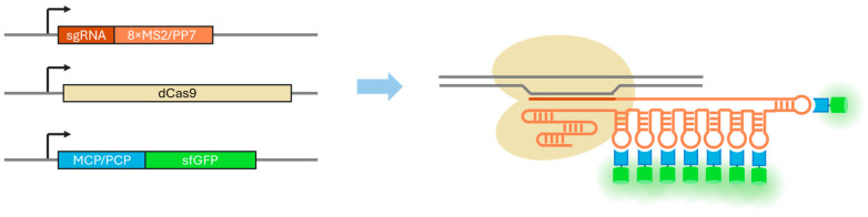
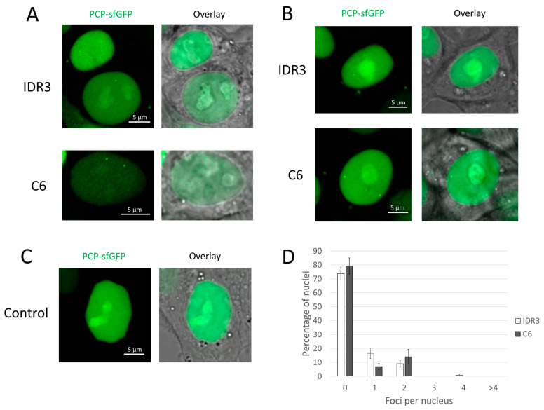
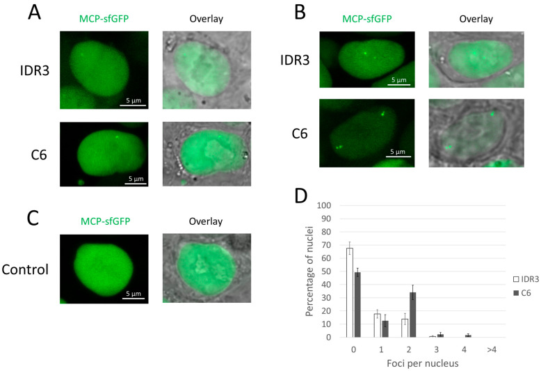
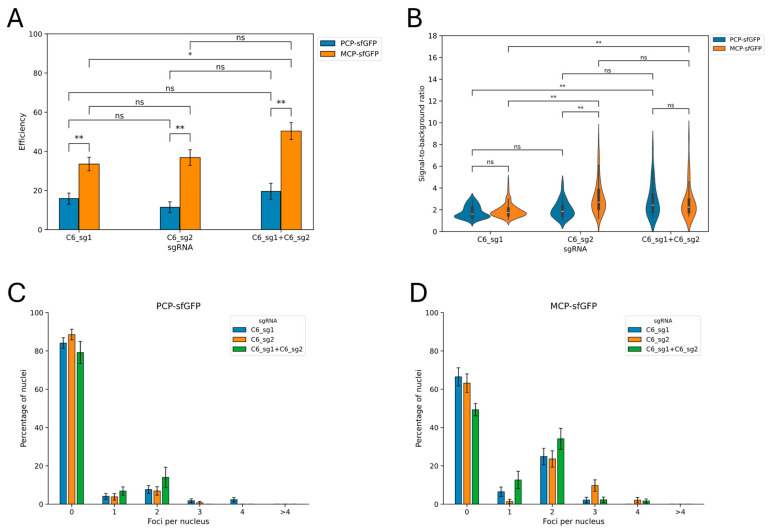
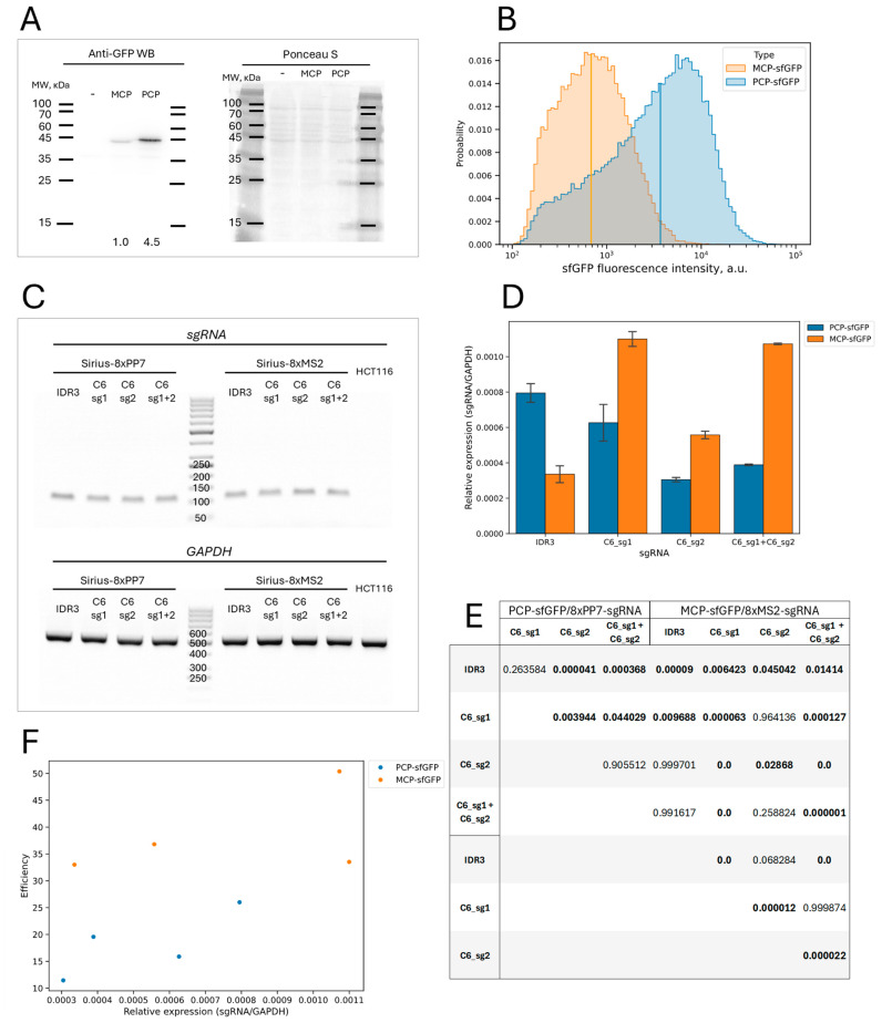
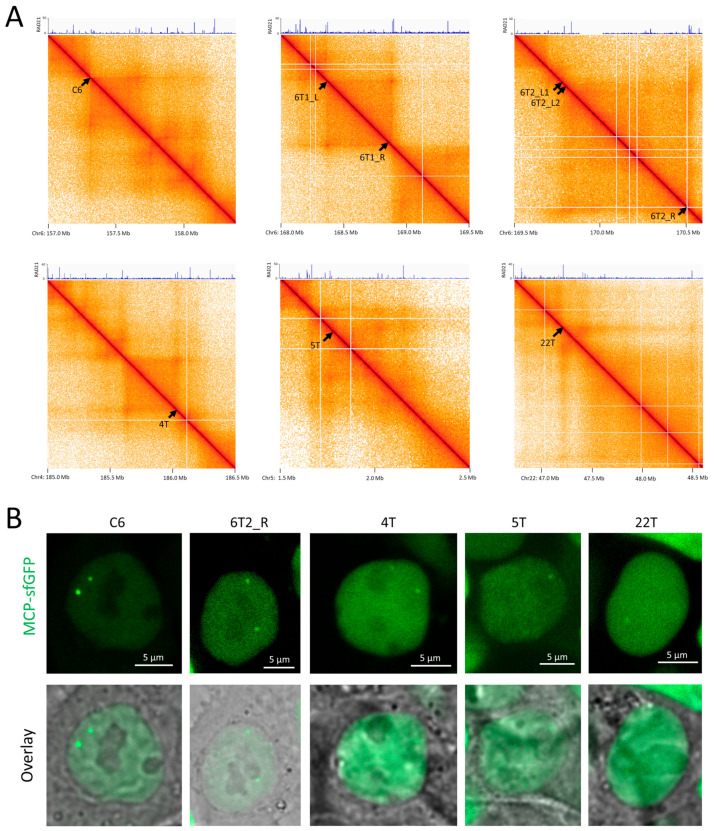
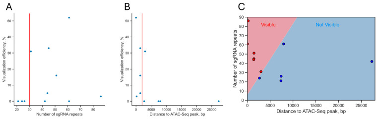
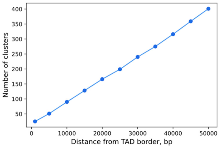
In recent years, various technologies have emerged for the imaging of chromatin loci in living cells via catalytically inactive Cas9 (dCas9). These technologies facilitate a deeper understanding of the mechanisms behind the chromatin dynamics and provide valuable kinetic data that could not have previously been obtained via FISH applied to fixed cells. However, such technologies are relatively complicated, as they involve the expression of several chimeric proteins as well as sgRNAs targeting the visualized loci, a process that entails many technical subtleties. Therefore, the effectiveness in visualizing a specific target locus may be quite low. In this study, we directly compared two versions of a previously published CRISPR-Sirius method based on the use of sgRNAs containing eight MS2 or PP7 stem loops and the expression of MCP or PCP fused to fluorescent proteins. We assessed the visualization efficiency for several unique genomic loci by comparing the two approaches in delivering sgRNA genes (transient transfection and lentiviral transduction), as well as two CRISPR-Sirius versions (with PCP and with MCP). The efficiency of visualization varied among the loci, and not all loci could be visualized. However, the MCP-sfGFP version provided more efficient visualization in terms of the number of cells with signals than PCP-sfGFP for all tested loci. We also showed that lentiviral transduction was more efficient in locus imaging than transient transfection for both CRISPR-Sirius systems. Most of the target loci in our study were located at the borders of topologically associating domains, and we defined a set of TAD borders that could be effectively visualized using the MCP-sfGFP version of the CRISPR-Sirius system. Altogether, our study validates the use of the CRISPR-Sirius technology for live-cell visualization and highlights various technical details that should be considered when using this method.

Keywords: 4D genome; CRISPR-Sirius; CRISPR-imaging; chromatin visualization; cohesin; live-cell microscopy; topologically associating domains (TADs).


Conflict of interest statement

The authors declare no conflicts of interest. The funders had no role in the design of the study; in the collection, analyses, or interpretation of the data; in the writing of the manuscript; or in the decision to publish the results.

Figures

Figure 1
Figure 1
The principle of the CRISPR-Sirius visualization technology. The genes for dCas9, sgRNA with eight MS2 or PP7 stem loops, and a stem-loop-binding protein (MCP or PCP) fused to a fluorescent protein (e.g., sfGFP) are expressed in cells. The complex consisting of dCas9, sgRNA-8xMS2/PP7, and PCP/MCP-sfGFP binds to a target genomic region, thereby allowing its visualization by fluorescent microscopy. The technology was originally described in 2018 by Ma et al. [22].
Figure 2
Figure 2
PCP-sfGFP version of the CRISPR-Sirius system. (AC) Examples of microscope images of HCT116_dCas9_PCP-sfGFP cells. (A) Transient transfection with plasmids containing sgRNA genes for IDR3 or C6 (48 h after transfection); (B) stable lentiviral transduction with sgRNA genes for IDR3 or C6; (C) control cells that did not express sgRNAs. In each case, (AC) show two images: in the sfGFP channel and an overlay of a fluorescent image on a corresponding bright field image. (D) The distribution of the number of observed foci in the nuclei of transduced cells with sgRNAs to IDR3 or C6. Mean values ± SEM after averaging by 10 fields of view for IDR3 (total 124 nuclei) and eight fields of view for C6 (a total 102 nuclei) are shown. No signals were visualized in any of the 257 imaged nuclei in control cells (a total of 17 fields of view).
Figure 3
Figure 3
MCP-sfGFP version of the CRISPR-Sirius system. (AC) Examples of microscope images of HCT116_dCas9_MCP-sfGFP cells. (A) Transient transfection with plasmids with sgRNA genes for IDR3 or C6 (48 h after transfection); (B) stable lentiviral transduction with sgRNA genes for IDR3 or C6; (C) control cells that did not express sgRNAs. In each case, (AC) show two images: the sfGFP channel and an overlay of a fluorescent image on a corresponding bright field image. (D) The distribution of the number of observed foci in the nuclei of transduced cells with sgRNAs to IDR3 or C6. Mean values ± SEM after averaging by 5 fields of view for IDR3 (total 138 nuclei) and 6 fields of view for C6 (total 131 nuclei) are shown. No signals were visualized in any of the 191 imaged nuclei in control cells (a total of 11 fields of view).
Figure 4
Figure 4
The results of the imaging efficiency analysis using one or two sgRNAs targeting the C6 locus. (A) Comparison of imaging efficiency using single or paired sgRNAs targeting the C6 locus. SgRNA genes were delivered by lentiviral transduction into cells expressing dCas9 and the corresponding type of stem-loop-binding proteins (HCT116_dCas9_PCP-sfGFP or HCT116_dCas9_PCP-sfGFP cells). The efficiency values are shown as the proportion of cells in which at least one signal was detected ± standard error for proportions; * p < 0.05, ** p < 0.005, ns: p > 0.05; two-proportion Z-test with Holm–Sidak correction for multiple comparisons. The total numbers of cells are 170, 185, 131, 144, 92, and 131 (the order corresponds to that on the graph). (B) Comparison of signal-to-background ratios using single or paired sgRNAs targeting the C6 locus. Violin plots correspond to kernel density estimation. The boxplots for corresponding samples are shown inside (white bar = median; box = interquartile range, whiskers = 1.5× interquartile range). ** p < 0.005, ns: p > 0.05, Mann–Whitney U-test with Holm–Sidak correction for multiple comparisons. The numbers of signals in each sample are 55, 116, 24, 124, 29, and 38 (the order corresponds to that on the graph). (C,D) The distribution of cells according to the number of visualized signals using the indicated guide RNAs, for two types of CRISPR-Sirius system: PP7/PCP-sfGFP (C) and MS2/MCP-sfGFP (D). The data values are the proportions of cells ± standard error for proportions.
Figure 5
Figure 5
Analysis of the expression of sgRNAs and stem-loop-binding proteins in two CRISPR-Sirius systems. (A) Western blot analysis of MCP-sfGFP and PCP-sfGFP protein levels in HCT116_dCas9_MCP-sfGFP and HCT116_dCas9_PCP-sfGFP cells, respectively, using anti-GPF antibodies. The molecular weights of several marker bands are indicated. The left image corresponds to the ECL detection of the target proteins; the right image is the result of membrane staining with Ponceau S for total protein normalization. The numbers below the lanes correspond to the relative intensity of the target band after normalization to the total protein. Lane “-” corresponds to an HCT116 cell lysate applied as a negative control. The expected molecular weights of the MCP-sfGFP and PCP-sfGFP proteins are 41.1 and 43.1 kDa, respectively, and these were consistent with the mobility of the proteins detected in the blot. (B) The distribution of HCT116_dCas9_MCP-sfGFP and HCT116_dCas9_PCP-sfGFP cells by sfGFP expression detected by flow cytometry. The vertical lines correspond to the medians of the distributions. (C) The qualitative analysis of the expression of sgRNAs. The electrophoresis of the products of the PCR amplification of cDNA from cells expressing the corresponding sgRNAs is shown. The sizes of several bands from the molecular length markers are indicated. Lane “HCT116” corresponds to HCT116 cells that did not express sgRNAs (negative control). The expected sizes of the PCR products were 107 bp for the sgRNA pair and 496 bp for the GAPDH pair. The expected sizes were consistent with the observed values. (D) The quantitative analysis of sgRNA expression by real-time PCR. Each column corresponds to a single cell culture expressing dCas9, MCP-sfGFP, or PCP-sfGFP and the indicated sgRNA(s). Values represent the mean ± SEM of the expression level relative to GAPDH gene expression for three independent RNA extractions. (E) p-values for the pairwise comparisons of the values shown in (D) using the Tukey HSD test. p-values lower than 0.05 are shown in bold. Values less than 1 × 10⁻⁶ are rounded to 0.0. The p-value for the preliminary one-way ANOVA was 2.9 × 10⁻⁹, allowing subsequent post hoc analysis by Tukey’s HSD test. (F) A scatter plot showing the values of the visualization efficiency against the relative expression of the sgRNAs shown in (D). No statistically significant correlation was found (Spearman correlation coefficient = 0.571, p-value = 0.139).
Figure 6
Figure 6
Visualization of the borders of topologically associating domains by CRISPR-Sirius. (A) Hi-C maps of the regions of designated chromosomes containing selected TAD borders (indicated by labeled arrows). ChIP-Seq profiles of fold enrichment for the RAD21 cohesin subunit are shown at the top of each map. The coordinates shown are for the hg38 human genome assembly. (B) Examples of microscope images of HCT116_dCas9_MCP-sfGFP cells transduced with visualizing gRNA genes for the indicated TAD borders.
Figure 7
Figure 7
The relationship between the visualization efficiency of a locus and the number of sgRNA repeats and the distance to ATAC-Seq peaks. (A) Scatter plot showing the visualization efficiency against the number of sgRNA repeats in a locus. The vertical red line corresponds to 30 repeats per cluster (a possible lower limit of repeats in the visualizable clusters). (B) Scatter plot showing the visualization efficiency against the distance to the nearest ATAC-Seq peak. The vertical red line corresponds to 2000 bp (a possible upper limit of the distance for the visualizable clusters). (C) The distribution of the studied loci by the distance to the ATAC-Seq peak and by the number of sgRNA repeats in the locus. Red dots are loci that we were able to visualize using CRISPR-Sirius, and blue dots are those that we were not able to visualize. The boundary between regions corresponds to the decision border for logistic regression (p-value = 0.0005).
Figure 8
Figure 8
The number of clusters with locus-specific repeats that could potentially be visualized by the CRISPR-Sirius technology as a function of the distance to the TAD boundary across the genome in HCT116 cells. The list of eligible repeats was taken from genome.ucf.edu/CRISPRbar [22]. TAD boundaries in HCT116 cells were taken from Rao et al., 2017 [34]. Only clusters with at least one boundary within the specified distance from a TAD boundary were counted.

Similar articles

References

    1. Huang S., Dai R., Zhang Z., Zhang H., Zhang M., Li Z., Zhao K., Xiong W., Cheng S., Wang B., et al. CRISPR/Cas-Based Techniques for Live-Cell Imaging and Bioanalysis. Int. J. Mol. Sci. 2023;24:13447. doi: 10.3390/ijms241713447. - DOI - PMC - PubMed
    1. Van Staalduinen J., van Staveren T., Grosveld F., Wendt K.S. Live-cell imaging of chromatin contacts opens a new window into chromatin dynamics. Epigenet. Chromatin. 2023;16:27. doi: 10.1186/s13072-023-00503-9. - DOI - PMC - PubMed
    1. Lu S., Hou Y., Zhang X.E., Gao Y. Live cell imaging of DNA and RNA with fluorescent signal amplification and background reduction techniques. Front. Cell Dev. Biol. 2023;11:1216232. doi: 10.3389/fcell.2023.1216232. - DOI - PMC - PubMed
    1. Maloshenok L.G., Abushinova G.A., Ryazanova A.Y., Bruskin S.A., Zherdeva V.V. Visualizing the Nucleome Using the CRISPR-Cas9 System: From in vitro to in vivo. Biochemistry. 2023;88:S123–S149. doi: 10.1134/S0006297923140080. - DOI - PMC - PubMed
    1. Thuma J., Chung Y.C., Tu L.C. Advances and challenges in CRISPR-based real-time imaging of dynamic genome organization. Front. Mol. Biosci. 2023;10:1173545. doi: 10.3389/fmolb.2023.1173545. - DOI - PMC - PubMed

Publication types

MeSH terms

LinkOut - more resources