. 2024 Sep 2;13(17):5196.
doi: 10.3390/jcm13175196.

Intraoral Scanning Enables Virtual-Splint-Based Non-Invasive Registration Protocol for Maxillofacial Surgical Navigation

Affiliations

Intraoral Scanning Enables Virtual-Splint-Based Non-Invasive Registration Protocol for Maxillofacial Surgical Navigation

Max Wilkat et al. J Clin Med. .

Abstract

Background/Objectives: Surgical navigation has advanced maxillofacial surgery since the 1990s, bringing benefits for various indications. Traditional registration methods use fiducial markers that are either invasively bone-anchored or attached to a dental vacuum splint and offer high accuracy but necessitate additional imaging with increased radiation exposure. We propose a novel, non-invasive registration protocol using a CAD/CAM dental splint based on high-resolution intraoral scans. Methods: The effectiveness of this method was experimentally evaluated with an ex vivo 3D-printed skull measuring the target registration error (TRE). Surgical application is demonstrated in two clinical cases. Results: In the ex vivo model, the new CAD/CAM-splint-based method achieved a mean TRE across the whole facial skull of 0.97 ± 0.29 mm, which was comparable to traditional techniques like using bone-anchored screws (1.02 ± 0.23 mm) and dental vacuum splints (1.01 ± 0.33 mm), while dental anatomical landmarks showed a lower accuracy with a mean TRE of 1.84 ± 0.44 mm. Multifactorial ANOVA confirmed significant differences in TRE based on the registration method and the navigated level of the facial skull (p < 0.001). In clinical applications, the presented method demonstrated high accuracy for both midfacial and mandibular surgeries. Conclusions: Our results suggest that this non-invasive CAD/CAM-splint-based method is a viable alternative to traditional fiducial marker techniques, with the potential for broad application in maxillofacial surgery. This approach retains high accuracy while eliminating the need for supplementary imaging and reduces patient radiation exposure. Further clinical trials are necessary to confirm these findings and optimize splint design for enhanced navigational accuracy.

Keywords: computer-assisted planning; intraoral scanning; maxillofacial surgery; navigational registration; surgical navigation.


Conflict of interest statement

The authors declare no conflicts of interest.

Figures
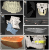
Figure 1
Figure 1
CAD/CAM of registration splint. Steps 1 to 7 are displayed as described in the text in detail, beginning with the intraoral scan of the upper and lower dentition (A). The second step of semi-automatic matching through the software IPS Case Designer is displayed (B). Next, an intermediate splint is generated following the mandible-first protocol with a high degree of mandibular autorotation of >10° (C). Modification of the splint design through Boolean subtraction is depicted using the freeware Autodesk Meshmixer (D). Final splint design (E) can be manufactured via 3D-printing using transparent surgical guide resin in orange color (F). For surgical navigation, the STL of the registration splint is imported into the Brainlab software iPlan 3.0.5 along with the DICOM data, and four virtual registration landmarks (red) can be positioned at the bottom of the indentations of the vestibular surface of the splint (yellow), perfectly aligning with the upper dentition (G).
Figure 2
Figure 2
Target registration error verification in three steps. (A) Firstly, one of four registration methods was chosen (M1: bone-anchored screws, M2: dental vacuum-splint with screws, M3: dental CAD/CAM splint, M4: dental landmarks). (B) For each run-through, the registration process for one method (here, the method M3 is shown as an example) was performed. The setup is illustrated on the left, featuring the navigation system’s infrared camera and monitor in the background. The detailed view in the middle image shows the 3D-printed skull with the skull reference array attached to the temporal bone and the upper dentition covered by the CAD/CAM registration splint. As the observer points to the four indentations on the registration splint, the system tracks the registration. Successful registration is confirmed by checking alignment at the monitor, either by pointing to the registration landmarks or anatomical landmarks. (C) Following successful registration, the mandible was secured with wires to the MMF screws in habitual occlusion. Using the navigation probe, the observer pointed perpendicularly to the camera view axis at each gutta-percha point. The system then displayed the estimated distance between the probe tip and the gutta-percha point, defined as the target registration error (TRE) value. TRE values were recorded twice for each of the 64 guttapercha points (32 green targets in the midface and 32 blue targets in the mandible), with the process repeated three times for each registration method—twice by the first observer and once by a second observer.
Figure 3
Figure 3
Mean target registration error (TRE) for each registration method M1–M4 separated into the region of the midface, of the mandible, and the whole facial skull. Whiskers show the standard deviation.
Figure 4
Figure 4
Point cloud plotting distance of the registration center in cm (x axis) versus the mean target registration error (TRE) in mm (y axis) in the midface for each registration method M1–M4. The regression line is displayed as dotted line.
Figure 5
Figure 5
Point cloud plotting distance of the registration center in cm (x axis) versus mean target registration error (TRE) in mm (y axis) in the mandible for each registration method M1–M4. Regression line is displayed as dotted line.
Figure 6
Figure 6
Mean TRE in mm at each level of the facial skull for each registration method M1–M4. Levels 0–2 group the targets across the mandible (0: ramus on both sides; 1: inferior mandibular border; 2: alveolar process of the mandible) while levels 3–6 group the targets across the midface (3: alveolar process of the maxilla; 4: maxillary sinus; 5: zygoma and infraorbital rim; 6: latero-orbital rim and posterior orbit). The registration center of each method is depicted as “X“ in the lateral and frontal view of the facial skull model.
Figure 7
Figure 7
Case 1—Secondary repair of misplaced zygoma and orbital floor reconstruction. (A) Comparison of pre- and postoperative face scans shows that the asymmetry of the eyelids due to the hypoglobus and enophthalmos of the atrophic eyeball could be corrected. (B) Laser-sintered, color-coded patient-specific implants with corresponding drilling and cutting guides. (C) Although the guides could not be correctly positioned due to pseudarthrosis, the reconstruction results regarding the repositioned zygoma and the orbital implant placements were successful with accurate positioning due to intraoperative surgical navigation, which was proved by post-surgical analysis via the matching of the postoperative CBCT scan to the planning data shown in multi-planar view.
Figure 8
Figure 8
Case 1—Secondary repair of misplaced zygoma and orbital floor reconstruction. Facilitated by pointer-based surgical navigation utilizing the non-invasive registration protocol involving the CAD/CAM registration splint (A), an intraoperative assessment of zygoma repositioning was possible (B) before proceeding with the next step of orbital implant placement for orbital floor reconstruction, which could again be checked for accurate positioning via surgical navigation (C). Note the fixation of the skull reference array on the contralateral side of the affected zygoma visible in (A).
Figure 9
Figure 9
Case 2—Mandibular Recontouring in a case of benign central osteoma. Preoperative (AD) and postoperative (FI) radiological scans and clinical photographs are depicted. The virtual plan is shown in (E) with the segmented affected right side of the mandible (red) illustrating the bulge of the osteoma. The unaffected healthy left side (blue) was mirrored and aligned to the right side (green), while the mandibular canal was segmented in yellow to visualize the course of the inferior alveolar nerve during surgery.
Figure 10
Figure 10
Case 2—Mandibular Recontouring in a case of benign central osteoma. Utilizing the TRIOS 3 from 3Shape (A) an intraoralscan was taken (B). This could be matched to the DICOM data along with virtual splint design, all made possible through the orthognathic planning software IPS Case designer from KLS Martin (not depicted, please refer to Figure 1). The virtual splint (yellow) can be loaded into the navigation software iPlan from Brainlab (C) to mark the registration landmarks in the splint‘s indentation (red). At the beginning of the surgery, the splint is put on to the upper dentition and registration landmarks are pointed at (D) until the system accepts the registration. After successful registration, results can be verified by checking the monitor (E) while pointing at anatomical landmarks (F). During the surgery, closing the mandible in habitual occlusion allowed for the use of navigation in the mandible (G), enabling the intraoperative verification of whether the virtually planned outcome had been achieved after recontouring (H).

Similar articles

Cited by

References

    1. Mezger U., Jendrewski C., Bartels M. Navigation in Surgery. Langenbecks Arch. Surg. 2013;398:501–514. doi: 10.1007/s00423-013-1059-4. - DOI - PMC - PubMed
    1. Demian N., Pearl C., Woernley T.C., Wilson J., Seaman J. Surgical Navigation for Oral and Maxillofacial Surgery. Oral. Maxillofac. Surg. Clin. N. Am. 2019;31:531–538. doi: 10.1016/j.coms.2019.06.001. - DOI - PubMed
    1. Azarmehr I., Stokbro K., Bell R.B., Thygesen T. Surgical Navigation: A Systematic Review of Indications, Treatments, and Outcomes in Oral and Maxillofacial Surgery. J. Oral. Maxillofac. Surg. 2017;75:1987–2005. doi: 10.1016/j.joms.2017.01.004. - DOI - PubMed
    1. Sukegawa S., Kanno T., Furuki Y. Application of Computer-Assisted Navigation Systems in Oral and Maxillofacial Surgery. Jpn Dent. Sci. Rev. 2018;54:139–149. doi: 10.1016/j.jdsr.2018.03.005. - DOI - PMC - PubMed
    1. Harmsen S., Teraphongphom N., Tweedle M.F., Basilion J.P., Rosenthal E.L. Optical Surgical Navigation for Precision in Tumor Resections. Mol. Imaging Biol. 2017;19:357–362. doi: 10.1007/s11307-017-1054-1. - DOI - PMC - PubMed

LinkOut - more resources