. 2024 Sep 18;13(1):256.
doi: 10.1038/s41377-024-01580-5.

Optical fibre based artificial compound eyes for direct static imaging and ultrafast motion detection

Affiliations

Optical fibre based artificial compound eyes for direct static imaging and ultrafast motion detection

Heng Jiang et al. Light Sci Appl. .

Abstract

Natural selection has driven arthropods to evolve fantastic natural compound eyes (NCEs) with a unique anatomical structure, providing a promising blueprint for artificial compound eyes (ACEs) to achieve static and dynamic perceptions in complex environments. Specifically, each NCE utilises an array of ommatidia, the imaging units, distributed on a curved surface to enable abundant merits. This has inspired the development of many ACEs using various microlens arrays, but the reported ACEs have limited performances in static imaging and motion detection. Particularly, it is challenging to mimic the apposition modality to effectively transmit light rays collected by many microlenses on a curved surface to a flat imaging sensor chip while preserving their spatial relationships without interference. In this study, we integrate 271 lensed polymer optical fibres into a dome-like structure to faithfully mimic the structure of NCE. Our ACE has several parameters comparable to the NCEs: 271 ommatidia versus 272 for bark beetles, and 180o field of view (FOV) versus 150-180o FOV for most arthropods. In addition, our ACE outperforms the typical NCEs by ~100 times in dynamic response: 31.3 kHz versus 205 Hz for Glossina morsitans. Compared with other reported ACEs, our ACE enables real-time, 180o panoramic direct imaging and depth estimation within its nearly infinite depth of field. Moreover, our ACE can respond to an angular motion up to 5.6×10⁶ deg/s with the ability to identify translation and rotation, making it suitable for applications to capture high-speed objects, such as surveillance, unmanned aerial/ground vehicles, and virtual reality.


Conflict of interest statement

The authors declare no competing interests.

Figures

Fig. 1
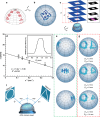
Fig. 1. Concept and principle of the artificial compound eye for a panoramic camera (ACEcam) that uses conical-microlens optical fibres to mimic natural ommatidia.
a The fly Choerades fimbriata has natural compound eyes (NCEs) for imaging; photograph courtesy of Mr. Thorben Danke of Sagaoptics. The inset shows compactly arranged corneal facet lenses in the NCEs. b In a natural ommatidium, the facet lens with a focal length f collects light at a specific acceptance angle Δφ, the crystalline cone ensures light convergence, the rhabdom (diameter d) transmits light through the inner structure, and the photoreceptor cell records the light information. c An NCE consists of numerous natural ommatidia, which are surrounded by pigment cells to prevent crosstalk. Here, the interommatidial angle ∆Φ = D/R, where D and R denote the arc distance of adjacent ommatidia and the local radius of curvature, respectively. d Comparison of different compound eyes in the functions of static panoramic imaging and dynamic motion detection. The 1st generation ACEs primarily focused on the fabrication of ACE microlenses, lacking the ability of static imaging or dynamic detection. In the 2nd generation ACEs, none of these ACEs could realise real-time panoramic direct imaging and dynamic motion detection simultaneously, as what the NCEs can do. In contrast, our ACEcam is comparable to the NCEs in aspects of 180o field of view and static imaging, and surpasses the NCEs in ultrafast motion detection. e An artificial ommatidium closely resembles a natural ommatidium by using a microlens to mimic the facet lens and the crystalline cone, an optical fibre core to mimic the rhabdom, an optical fibre cladding to mimic the pigment cells, an imaging lens to mimic synaptic units to focus each optical fibre onto an individual photodetector, and a photodetector in the flat imaging sensor chip to mimic the photoreceptor cell. f An artificial compound eye consists of numerous artificial ommatidia, with a flat imaging sensor chip mimicking the deeper neural centres (medulla and lobula), where signals are pre-processed. The signals are then transmitted to a computer for further analysis
Fig. 2
Fig. 2. Operating principles and fabrication of the ACEcam.
a Scanning electron microscopy (SEM) image of the conical microlens on an optical fibre. b Top view of the ACEcam light receiving head that uses a 3D-printed dome to host 271 fibre ends. c Photograph of an assembled ACEcam. d Concept of image formation. Using a + line-art pattern as the object (top panel), some fibres receive light from the object (second panel), and this pattern is transmitted from the lens end to the other end of the fibre (third panel). An imaging lens is employed to project the light from the fibre ends to a flat imaging sensor chip (fourth panel top), which is then converted into the final digital image (bottom panel). e Fabrication process flow of conical microlens optical fibres. A template with an array of conical grooves is fabricated by an ultrahigh precision 3D printing method (top panel), then the first PDMS mould is made to obtain convex cones (second panel). Physical vapour deposition and electroplating are then utilised to coat Cu layers on the first PDMS mould to smooth the rough surface of the convex cones and to round the sharp tip of the convex cones (third panel). After the second pattern transfer to get the second PDMS mould, optical adhesive NOA81 is dropped (0.15 μL/drop) into each conical groove by using a microsyringe (fourth panel). Next, an optical fibre buncher is mounted on the second PDMS mould so that optical fibres are well aligned with and submerged into the NOA81 microlenses wells. After UV illumination, each optical fibre end is mounted with a conical microlens, and finally, all fibres are peeled off (bottom panel)
Fig. 3
Fig. 3. Static imaging and depth estimation of the ACEcam.
a Combined image of a laser spot from nine angles (from −90o to 90o in both the x and y directions at a step of 22.5o). b Image of the logo of The Hong Kong Polytechnic University. c, d Depth estimation using the linear relationship between the point spread parameter σ and the reciprocal of the object distance u−1. In (c), example images at four different distances u1 = 3 mm, u2 = 5 mm, u2 = 7 mm, and u4 = 9 mm are shown in the dotted box. In the image acquired at each distance, the grey values along four parallel lines (shown here in pink) in the x direction are analysed to calculate the mean value and the errors shown in (d). DL is the distance between a point on the pink line and the upper boundary of an image. In (d), the inset shows the relative grey value distribution along one sample pink line in c. A low error range signifies a high reliability of ACEcams depth estimation. e, Images of the letters ‘HK’ captured at three different polar angles relative to the centre of the camera: −50o (top), 0o (centre) and 50o (bottom). f Schematic of an experimental setup to verify the nearly infinite depth of field of ACEcam. Objects A (circle) and B (triangle) are placed at angular positions of −40o and 40o. g Images of the circle and triangle patterns when the distance of the circle image is fixed at DA = 2 mm and the distance of the triangle image varies from DB = 2, 8 to 14 mm
Fig. 4
Fig. 4. Dynamic motion detection of the ACEcam.
a Optical flow as the ACEcam is translated in front of a checkerboard pattern at a distance of 10 mm. Here green dots represent the ommatidia illuminated by bright squares of the checkerboard, and the direction and length of the vector denote the motion direction and velocity of a bright square. b Optical flow as the ACEcam is rotated, with the dark spot indicating the calculated rotation centre. c Experimental setup to generate very high angular velocities for the dynamic response measurement. Five LEDs are evenly spaced along 180o and lit up successively with a delay time ∆t whose minimum value is equal to the response time of the photodiode Δtdec, and five photodiodes are employed to record the light emitted by the corresponding LEDs. d, e Response signals of the photodiodes (upper panel) when the LEDs are driven by square waves (lower panel) of fflicker = 240 Hz in (d) and 31.3 kHz in (e). f Signal transmission pathway in the natural ommatidium. g Signal transmission pathway in the artificial ommatidium
Fig. 5
Fig. 5. 3D-printed components for the assembly of ACEcam.
a Photograph of the perforated dome, held by tweezers. b Design of the perforated dome. c Photograph of the perforated buncher. d Design of the screwed hollow tube that will be used to hold the dome and the buncher
Fig. 6
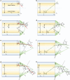
Fig. 6. Light paths in different optical fibres for the analysis of the divergence angles (or equivalently, the acceptance angles).
Red paths represent the light reflected from the upper core/cladding interface of the optical fibre, and green paths represent the light reflected from the lower core/cladding interface of the optical fibre. a, b In the bare multimode optical fibre, the light can be reflected from the upper (a) or lower (b) core/cladding interface. c,d In the optical fibre capped with a spherical microlens, the light can be reflected from the upper (c) or lower (d) core/cladding interface. eh In the optical fibre capped with a conical microlens, the light has various paths. In one case, the light experiences no reflection in the conical surface after being reflected from the upper (e) or lower (f) core/cladding interface. In the other case, the light experiences one hop (i.e., reflection) in the conical surface after being reflected from the upper (g) or lower (h) core/cladding interface
Fig. 7
Fig. 7. Comparison of the acceptance (divergence) angles of the plastic optical fibres with spherical or conical microlenses, with red paths representing the light emitted directly from the bare end of plastic optical fibres, and green paths representing the light emitted from microlenses.
a The spherical microlens has a larger acceptance angle than the flat-end optical fibre (i.e., φ3 > φ1). b The conical microlens has a smaller acceptance angle (i.e., φ2 < φ1). Therefore, the use of conical microlenses can effectively narrow the acceptance angle
Fig. 8
Fig. 8. Acceptance angle as a function of the half-apex angles θ of the conical microlens.
The theoretical analysis is presented using three distinct colour lines to illustrate different scenarios. (1) When θ ≥ 43o, the green line represents the case in which light is directly emitted from the conical surface of the microlens without any reflection, and there is no hollow region within the emission pattern. However, the acceptance angle is too large ( > 60o). (2) When 31o ≤ θ < 43o, the cyan line represents the case in which light is directly emitted from the conical surface of the microlens without reflection. The acceptance angle is narrowed when θ goes smaller, but a hollow central region appears in the emission pattern. Equivalently, if the fibre collects light, the information in the central hollow region cannot be detected, which is unfavourable. The star highlights the working conditions used in our experiments, i.e., θ = 35o and an acceptance angle of 45o. By rounding the sharp tip of the cone, the hollow central region can be eliminated from the emission pattern (the inset in the lower right part). (3) When θ < 31o, the red line represents the case in which the light undergoes a single reflection (or hop) in the conical microlens. The hollow central region reappears and the transmitted light intensity is very low. Therefore, this case is not suitable for collecting the light
Fig. 9
Fig. 9. Fabrication process flow of conical microlens optical fibres.
a A 3D-printed template with an array of conical grooves and 4 protruded ‘+‘ alignment markers at the corners. The enlarged view shows that the conical surface of each groove has a layered texture and is not smooth. b Polydimethylsiloxane (PDMS) is used to transfer patterns. c The first PDMS mould. d Physical vapour deposition (PVD) and electroplating. e Cu-coated mould. The inset shows that the layered texture is smoothened and the tip of the cone is rounded. f PDMS is used to transfer patterns again. g The second PDMS mould with conical grooves. h The same volume (~0.15 μL) of NOA81 liquid is deposited into each conical groove. i A 3D-printed optical fibre buncher with many through holes. j UV light is used to cure the conical microlenses on top of the optical fibres

References

    1. Hooke, R. Micrographia, or, Some Physiological Descriptions of Minute Bodies Made by Magnifying Glasses: with Observations and Inquiries Thereupon (Jo. Martyn and Ja. Allestry, 1665).
    1. Darwin, C. R. On the Origin of Species by Means of Natural Selection, or the Preservation of Favoured Races in the Struggle for Life. (John Murray, London, 1859). - PMC - PubMed
    1. Exner, S. Die Physiologie der Facettirten Augen von Krebsen und Insecten: Eine Studie. (Franz Deuticke, Leipzig, 1891).
    1. Agi, E. et al. The evolution and development of neural superposition. J. Neurogenet.28, 216–232 (2014). - PMC - PubMed
    1. Shinomiya, K. et al. The organization of the second optic chiasm of the Drosophila optic lobe. Front. Neural Circuits13, 65 (2019). - PMC - PubMed

LinkOut - more resources