

Comparison of the Effects of Different Palatal Morphology on Maxillary Expansion via RME and MSE: A Finite Element Analysis
- PMID: 39295434
- PMCID: PMC11411151
- DOI: 10.1002/cre2.70005
Comparison of the Effects of Different Palatal Morphology on Maxillary Expansion via RME and MSE: A Finite Element Analysis
Abstract
Objectives: This study aims to compare and analyze the biomechanical effect and the displacement trend of RME and MSE on the maxillofacial complex under different palatal shapes by using finite element analysis.
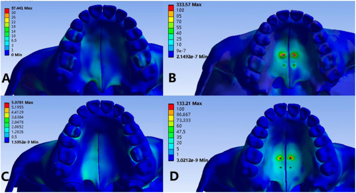
Methods: The three-dimensional model of maxillofacial complex was obtained from a computed tomography image of a person with a normal palate. Then, we modified the shape of the palate to obtain the model with a high palate. Additionally, two expander devices were considered. MSE and RME were created and four models were made: Model 1: Normal-palate craniomaxillofacial complex with RME expander; Model 2: Normal-palate craniomaxillofacial complex with MSE expander; Model 3: High-palate craniomaxillofacial complex with RME expander; Model 4: High-palate craniomaxillofacial complex with MSE expander. Then, lateral forced displacement was applied and the analysis results were obtained.
Results: The lateral displacement of the palatal suture of Model 3 is greater than that of Model 1, and the maxilla has more rotation. The crown/root ratio of Model 1 is significantly greater than that of the other three groups. Compared with Model 1, Model 3 has greater stress concentration in the superstructure of the craniomaxillofacial complex. Both of them have greater stress in the anchorage area than Model 2 and Model 4.
Conclusion: Different shapes of the palate interfere with the effects of RME and MSE, and its influence on the stress distribution and displacement of the craniomaxillary complex when using RME is greater than MSE. The lateral displacement of the palatal suture of MSE is significantly larger than that of RME. It is more prone to tipping movement of the anchor teeth using RME under normal palate, and MSE may manage the vertical control better due to the smaller crown/root ratio than RME and intrusive movement of molars.
Keywords: MSE; RME; finite element analysis; maxillary expansion; palatal morphology.
© 2024 The Author(s). Clinical and Experimental Dental Research published by John Wiley & Sons Ltd.
Conflict of interest statement
The authors declare no conflicts of interest.
Figures


References
-
- Araugio, R. M. S. , Landre J. Jr., Silva D. L. A., Pacheco W., Pithon M. M., and Oliveira D. D.. 2013. “Influence of the Expansion Screw Height on the Dental Effects of the Hyrax Expander: A Study With Finite Elements.” American Journal of Orthodontics and Dentofacial Orthopedics 143, no. 2: 221–227. - PubMed
-
- Asscherickx, K. , Govaerts E., Aerts J., and Vande Vannet B.. 2016. “Maxillary Changes With Bone‐Borne Surgically Assisted Rapid Palatal Expansion: A Prospective Study.” American Journal of Orthodontics and Dentofacial Orthopedics 149, no. 3: 374–383. - PubMed
-
- Bezerra, T. P. , Silva F. I., Scarparo H. C., Costa F. W. G., and Studart‐Soares E. C.. 2013. “Do Erupted Third Molars Weaken the Mandibular Angle After Trauma to the Chin Region? A 3D Finite Element Study.” International Journal of Oral and Maxillofacial Surgery 42, no. 4: 474–480. - PubMed
Publication types
MeSH terms
LinkOut - more resources
Full Text Sources
