Review
. 2024 Sep 20;17(1):2.
doi: 10.1007/s40820-024-01498-y.

Advancements and Challenges in Organic-Inorganic Composite Solid Electrolytes for All-Solid-State Lithium Batteries

Affiliations
Review

Advancements and Challenges in Organic-Inorganic Composite Solid Electrolytes for All-Solid-State Lithium Batteries

Xueyan Zhang et al. Nanomicro Lett. .

Abstract

To address the limitations of contemporary lithium-ion batteries, particularly their low energy density and safety concerns, all-solid-state lithium batteries equipped with solid-state electrolytes have been identified as an up-and-coming alternative. Among the various SEs, organic-inorganic composite solid electrolytes (OICSEs) that combine the advantages of both polymer and inorganic materials demonstrate promising potential for large-scale applications. However, OICSEs still face many challenges in practical applications, such as low ionic conductivity and poor interfacial stability, which severely limit their applications. This review provides a comprehensive overview of recent research advancements in OICSEs. Specifically, the influence of inorganic fillers on the main functional parameters of OICSEs, including ionic conductivity, Li+ transfer number, mechanical strength, electrochemical stability, electronic conductivity, and thermal stability are systematically discussed. The lithium-ion conduction mechanism of OICSE is thoroughly analyzed and concluded from the microscopic perspective. Besides, the classic inorganic filler types, including both inert and active fillers, are categorized with special emphasis on the relationship between inorganic filler structure design and the electrochemical performance of OICSEs. Finally, the advanced characterization techniques relevant to OICSEs are summarized, and the challenges and perspectives on the future development of OICSEs are also highlighted for constructing superior ASSLBs.

Keywords: Characterization techniques; Composite solid electrolytes; Inorganic filler; Interfacial stability; Li-ion conduction mechanism.


Conflict of interest statement

The authors declare no interest conflict. They have no known competing financial interests or personal relationships that could have appeared to influence the work reported in this paper.

Figures

Fig. 1
Fig. 1
Scope and content diagram are discussed in this review
Fig. 2
Fig. 2
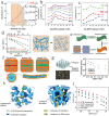
a Size distribution of LLZTO nanoparticles determined by a laser particle size analyzer. b Ion conductivities of PEO: LLZTO membranes with different volume fractions of LLZTO in size of D50 = 43 nm. c Ionic conductivity as a function of LLZTO volume fraction for LLZTO particles with different sizes [61], Copyright 2016, Elsevier. d Ion conductivities of PAN/LiClO4, PAN/LiClO4 with LLTO nanowires, and LLTO nanoparticles and the comparison of possible lithium-ion conduction pathway in nanowire-filled and nanoparticle-filled composite electrolytes [64], Copyright 2015, American Chemical Society. e Schematic diagram of garnet nanosheets and comparing composite electrolytes consisting of garnet nanoparticles [66], Copyright 2019, American Chemical Society. f Li-ion conduction pathways in OICSEs with nanoparticles, random nanowires, and aligned nanowires [67], Copyright 2017, Springer Nature Limited. g Ionic conductivity of vertically aligned, random, and polymer [68], Copyright 2017, American Chemical Society. h Schematics of agglomerated nanoparticles and 3D continuous framework. i Ionic conductivity of LLTO framework, LLTO nanoparticle, and silica particle OICSEs [69], Copyright 2018 Wiley
Fig. 3
Fig. 3
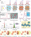
a 6Li NMR spectra of 5, 20, and 50 wt% LLZO-PEO/LiTFSI and 50 wt% LLZO-PEO/LiTFSI with TEGDME OICSEs before and after cycling and the corresponding Li-ion transport pathways [90], Copyright 2018, American Chemical Society. b 6Li NMR spectra of the LCPE-60 OICSEs before and after cycling and the Li-ion pathways [88], Copyright 2023 Elsevier. c 6Li NMR spectra of PAN (LiClO4)-5 wt% LLZO NWs OICSEs before and after cycling [92], Copyright 2017, American Chemical Society. d 6Li MAS NMR of an LGPS-PEO (LiTFSI) OICSE before and after cycling [93], Copyright 2019, American Chemical Society. e Schematic illustration of the ion conduction pathway along the space charge regions [94], Copyright 2018 American Chemical Society. f Schematic diagram of the interface of H-OISE, OISE, and OISE-L Copyright 2024 Wiley‐VCH GmbH [96]
Fig. 4
Fig. 4
a Schematic diagram of the interaction between PEO chains and Al2O3 surface groups [109], Copyright 2004, Kluwer Academic Publishers. b Preparation process of SiO2-UPy and schematic diagram of SHCPE with supermolecule network structure [110], Copyright 2019 Royal Society of Chemistry. c Morphology and synthesis diagram of the PEO-LiClO4-SiO2 OICSEs [111], Copyright 2020 American Chemical Society. d Preparation process diagram of p–V–SiO2/PEO cross-linked OICSEs [113], Copyright 2021 Elsevier. e Synthetic routes of the PAN- insitu-SiO2 OICSEs [114]. f Preparation process diagram of hollow PDA composite nanospheres and the TEM images of hollow SiO2 and hollow PDA composites [115], Copyright 2022, American Chemical Society
Fig. 5
Fig. 5
a Schematic illustration for Li-ion transport with nanoparticle and nanowire fillers [135], Copyright 2016, American Chemical Society. b Schematics of lithium-ion migration in Mg2B2O5 enhanced OICSEs [139], Copyright 2018, American Chemical Society. c Schematic diagram of TDI modified TiO2 and OICSE preparation [140], Copyright 2021 Elsevier. d Schematic diagram for the OICSEs fabrication procedure [141], Copyright 2022 Royal Society of Chemistry. e Schematic illustration depicting the formation of OICSEs incorporating silica nanotubes with hollow nanostructures [142] Copyright, 2020 Elsevier. f A mechanism to improve ionic conductivity by adding HNTs [143], Copyright 2018 Royal Society of Chemistry. g Schematic diagram of PEO-based HNTs electrolyte [144], Copyright 2019, American Chemical Society
Fig. 6
Fig. 6
a Voltage–time profiles of Li||GO-PEO||Li at 60 °C and cyclic performance of full battery at 1C [149], Copyright 2021, American Chemical Society. b Schematic diagram of the preparation of LiDGO nanosheets [150], Copyright 2020 Elsevier. c Schematic diagram of ion migration mechanism of LiMNT interlayer insertion into PEC-based electrolyte [152], Copyright 2019 WILEY. d Schematic diagram of the manufacturing process of GPE/VAMMT [153], Copyright 2022 Xinyang Li. e Schematic diagram of heat transfer in electrolytes with and without BN additives [155], Copyright 2020 Guangyuan Wesley Zheng. f Schematic diagram of the manufacturing containing MXene mSiO2 [157], Copyright 2020 WILEY
Fig. 7
Fig. 7
a Schematics of OICSEs with three types of geometrical structures. b Ionic conductivity in different regions of composite electrolytes [158], Copyright 2018, American Chemical Society. c Schematic illustration for preparation of PEO@GFC-25%ILs [160], Copyright 2020 Elsevier. d Schematic diagram of the microstructure of OICSEs containing 3D SiO2 aerogel [161], Copyright 2018 WILEY
Fig. 8
Fig. 8
a Process flow diagram of in-situ preparation of PEO-Li3PS4 OICSE [188], Copyright 2018 Elsevier. b Schematic illustration of OICSE and Arrhenius plots of Li7PS6, OICSE, and PVDF-HFP/LiTFSI polymer electrolyte. [189], Copyright 2020, American Chemical Society. c Cycling performance of modified Li6PS5Cl-PEO and Li in alloy cathodes [190], Copyright 2020 Elsevier. d Schematic illustration of LPSCl@P(VDF-TrFE) OICSEs via an electrospinning-infiltration hot-pressing method. e Long-term cycling performance of LPSCl@P(VDF-TrFE) OICSEs at 1.0 mA cm−2 [191], Copyright 2022 Wiley. f Cryo-TEM characterization of the Li/PEO interfaces. g Cryo-TEM characterization of the Li/S-CPE interfaces. h EDS elemental maps of S-CPE [192], Copyright 2022 Wiley
Fig. 9
Fig. 9
a Schematic illustration of an integrated LiFPO4/CSE/Li battery [206], Copyright 2018 WILEY. b Schematic illustration for the preparation of LLZO/PEO-LiTFSI electrolyte [207] Copyright 2019 WILEY. c Schematic of multiscale aligned mesoporous garnet LLZO membrane incorporated with PEO polymer [208], Copyright 2019, American Chemical Society. d Schematic diagram of dopamine polymerization on the LLZTO surface to form a polydopamine coating and the dispersion of LLZTO particles (coated and uncoated with PDA) in PEO solution [209], Copyright 2019 Royal Society of Chemistry. e Schematic diagram of the synthesis route for grafting molecular brushes onto LLZTO surface (MB-LLZTO) [211], Copyright 2019 Royal Society of Chemistry. f Preparation process diagram of an OICSE that forms a "bridge" between polymer and ceramic phase [212], Copyright 2023 Elsevier. g Schematic diagram of tape casting and battery manufacturing of PVDF/Al LLZO film on composite electrodes [214], Copyright 2023, American Chemical Society. h Preparation method and characterization diagram of PAN/LiClO4: LLZTO film [215], Copyright 2020, American Chemical Society
Fig. 10
Fig. 10
a Schematic diagram of 3D composite fiber network reinforced CPE preparation [226], Copyright 2022 Elsevier. b Schematic diagram of 3D porous LATP framework. c SEM images of 3D porous LATP frameworks with different NaCl template mass fractions [227], Copyright 2021 Elsevier. d Schematic diagram of the synthesis process and conduction mechanism of LATP@PMMA-PVDF electrolytes [228], Copyright 2021 Elsevier. e Schematic illustration for the synthesis of OICSE [229], Copyright 2017, American Chemical Society. f Schematic diagram of LiFePO4 | LAGP/30% PPC | Li batteries forming a LiF protective layer [230], Copyright 2019, American Chemical Society. g Schematic diagram of Li/PEO (LiTFSI)@LAGP-PEO (LiTFSI)/LiMFP batteries preparation [231], Copyright 2017, American Chemical Society. h Schematic diagram of LATP and PVDF@LATP@PVDF electrolytes at 0.1 mA cm−2. i Cross-sectional and surface SEM images of the LATP pellet [232], Copyright 2022, American Chemical Society
Fig. 11
Fig. 11
a Schematic diagram of 3D-CPEs preparation and Li plating and stripping cycling voltage profiles for the SPE and 3D-CPE [234], Copyright 2018, American Chemical Society. b Schematic diagram of ion transport paths for OICSE with mechanically mixed LLTO and OICSE with vertically aligned LLTO framework. c Li plating and stripping cycling voltage profiles for the PEO-LiTFSI and Ice-LLTO-PEO-LiTFSI [235], Copyright 2020 Elsevier. d Schematic diagram of cross-linked polyethylene oxide solid polymer electrolyte preparation. e Schematic diagram of three-dimensional fiber network OICSE composed of nanofibers and cross-linked polyethylene oxide solid polymer [236], Copyright 2019, Donghua University. f Schematic diagram of dual semi-solid polymer electrolyte films preparation [238], Copyright 2021, American Chemical Society
Fig. 12
Fig. 12
a 7Li MAS NMR spectra of PEO(LiTFSI)-LLZO OICSE. b 7Li 2D EXSY NMR spectrum with mixing times of 0.0001 s and 0.6 s, respectively [248], Copyright 2019, American Chemical Society. c 2D 1H–1H NOESY spectra of the mixtures of LiTFSI-PEO-Li6PS5Cl with PP13-TFSI ILs measured with tmix of 0.001, 0.01 and 0.1 s. [249], Copyright 2022 Marnix Wagemake. d 7Li 3D MRI images of the electrochemically cycled Li10GeP2S12 and PEO-coated Li10GeP2S12 electrolyte. e Histograms of normalized Li density at different depths of the cycled Li10GeP2S12 and PEO-coated Li10GeP2S12 electrolyte, respectively [250], Copyright 2018, American Chemical Society
Fig. 13
Fig. 13
a Normalized TOF–SIMS depth profiles of CsLi2P, Li2ZrO4, and Zr, representing Li3P and Li8ZrO6 reacted species, and bulk LiZr2(PO4)3, respectively. b 3D view of the sputtered volume in panel a. c A direct comparison of CsLi2P and Li2ZrO4, depth profiles obtained from the fresh composite membrane, the composite membrane after interaction with lithium metal, and the composite membrane after cycling the Li/Li symmetric cell. d TOF–SIMS high-resolution secondary ion maps of a Li/electrolyte cross-section [85], Copyright 2020, American Chemical Society. e HAADF-TEM images of PAN/LiClO4 and the PAN/LiClO4: LLZTO and corresponding EELS element concentration distribution map. f EELS spectra of selected regions of organic particle phase, organic/organic interface and polymer phase, polymer/inorganic interface [215], Copyright 2020, American Chemical Society
Fig. 14
Fig. 14
a SAXS curves of the pristine PEO (without Li salts) and PEO/LiFSI electrolytes at 25 and 60 °C. b SAXS curves of PEO/LiTFSI/LLZO were multiplied by 1.07 (~ 1/0.93) to normalize the scattering intensity for the less fraction of PEO/LiTFSI due to the added 0.07 (7%) LLZO [251] Copyright 2024, American Chemical Society. c SEM cross-sectional view of p-LATP, 3D reconstruction image of p-LATP and corresponding 2D sliced images from x–y, x–z plane [252] Copyright 2021, Wiley‐VCH GmbH. d In-situ c -AFM characterization of Li-ion migration in pure PEO(LiClO4) and 50 wt% LLZO-PEO(LiClO4) at 55 °C. e In-situ c-AFM characterization of Li-ions migration in 75 wt% LLZO-PEO(LiClO4) at 30 and 55 °C. f c-AFM current curve at grain boundaries, where grain boundary 1 and grain boundary 2 [253] Copyright 2021 Elsevier B.V

Similar articles

Cited by

References

    1. M. Li, J. Lu, Z. Chen, K. Amine, 30 years of lithium-ion batteries. Adv. Mater. 30, 1800561 (2018). 10.1002/adma.201800561 - PubMed
    1. J.M. Tarascon, M. Armand, Issues and challenges facing rechargeable lithium batteries. Nature 414, 359–367 (2001). 10.1038/35104644 - PubMed
    1. F.-Q. Liu, W.-P. Wang, Y.-X. Yin, S.-F. Zhang, J.-L. Shi et al., Upgrading traditional liquid electrolyte via in situ gelation for future lithium metal batteries. Sci. Adv. 4, eaat5383 (2018). 10.1126/sciadv.aat5383 - PMC - PubMed
    1. L. Wang, T. Liu, T. Wu, J. Lu, Strain-retardant coherent perovskite phase stabilized Ni-rich cathode. Nature 611, 61–67 (2022). 10.1038/s41586-022-05238-3 - PubMed
    1. Y. Zhang, W. Zhao, C. Kang, S. Geng, J. Zhu et al., Phase-junction engineering triggered built-in electric field for fast-charging batteries operated at −30 °C. Matter 6, 1928–1944 (2023). 10.1016/j.matt.2023.03.026

LinkOut - more resources