. 2024 Oct 8;18(40):27738-27751.
doi: 10.1021/acsnano.4c10264. Epub 2024 Sep 25.

All-Optical Trapping and Programmable Transport of Gold Nanorods with Simultaneous Orientation and Spinning Control

Affiliations

All-Optical Trapping and Programmable Transport of Gold Nanorods with Simultaneous Orientation and Spinning Control

José A Rodrigo et al. ACS Nano. .

Abstract

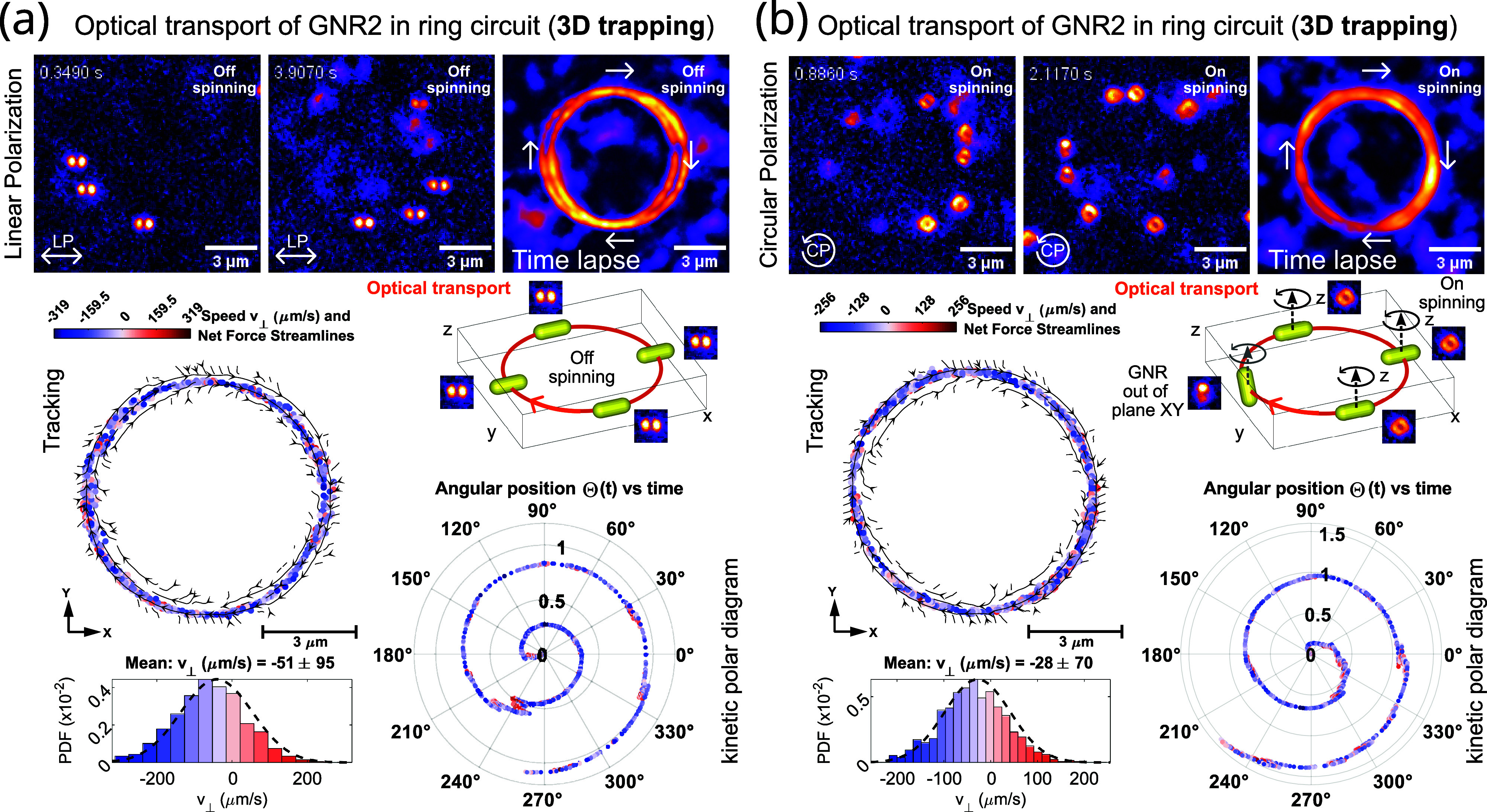
Gold nanorods (GNRs) are of special interest in nanotechnology and biomedical applications due to their biocompatibility, anisotropic shape, enhanced surface area, and tunable optical properties. The use of GNRs, for example, as sensors and mechanical actuators, relies on the ability to remotely control their orientation as well as their translational and rotational motion, whether individually or in groups. Achieving such particle control by using optical tools is challenging and exceeds the capabilities of conventional laser tweezers. We present a tool that addresses this complex manipulation problem by using a curve-shaped laser trap, enabling the optical capture and programmable transport of single and multiple GNRs along any trajectory. This type of laser trap combines confinement and propulsion optical forces with optical torque to transport the GNRs while simultaneously controlling their rotation (spinning) and orientation. The proposed system facilitates the light-driven control of GNRs and the quantitative characterization of their motion dynamics including transport speed, spinning frequency, orientation, and confinement strength. We experimentally demonstrate that remote control of the GNRs can be achieved both near a substrate surface (2D trapping) and deep within the sample (3D all-optical trapping). The motion dynamics of two sets of off-resonant GNRs, possessing similar aspect ratios but different resonance wavelengths, are analyzed to highlight the role played by their optical and mechanical properties in the optical manipulation process. The experimental results are supported by a theoretical model describing the observed motion dynamics of the GNRs. This optical manipulation tool can significantly facilitate applications of light-driven nanorods.

Keywords: gold nanorods; laser trap-and-transport; nanomotors; optical tweezers; plasmonics.


Conflict of interest statement

The authors declare no competing financial interest.

Figures

Figure 1
Figure 1
(a) Sketch of the optical setup required for the optical manipulation of the GNRs, their orientation detection, and measurement of their spinning frequency (by using a fiber-coupled balanced photodetector device, BPD). The spatial light modulator (SLM) allows the holographic generation of the laser traps. The optical refocusing module (ORM) allows for 3D darkfield imaging (through optical axial scanning), along with 3D orientation detection of the GNRs (thanks to a Q-plate, as indicated in the ORM inset). (b) Intensity and phase distributions of the considered curve-shaped laser traps (ring and square circuits) are shown along with the measured darkfield images of multiple GNRs transported along them. See Methods for further details about acronyms and setup characteristics.
Figure 2
Figure 2
(a) PSDs of the measured intensity fluctuations eq 9 for the same GNR spinning at favg = 1.24, 3, and 7.78 kHz. The small peak observed at a frequency of fSLM = 422 Hz corresponds to residual intensity fluctuations caused by the SLM device operation. (b) Fit of the corresponding measured ACFs provides the value of favg and rotational decay time (τc) of the GNR. (c) Measured favg and τc (estimated from the ACF fitting) are represented as a function of the laser power for the same GNR. Note that in (c), laser power values used in (a) and (b) are also indicated. (d) Measured ACF (scatter plot) of the same spinning GNR (favg = 8.17 kHz) represented along the ACF (black line) obtained from the numerical simulation of the GNR motion. Measured PSD (e) and ACF (f) of a spinning GNR (favg = 13.5 kHz) optically trapped in 3D.
Figure 3
Figure 3
Experimental results. Optical transport of a single GNR (average size 65 × 162 nm2) along the ring circuit (a) and square circuit (b) for both linear (LP) and circular (CP) polarization. The value of the mean transport speed (see histograms) is indicated for each case (LP and CP). The tracking data of the GNR as well as the kinetic polar diagram are displayed for CP, for both the ring circuit (a) and square circuit (b). (c) PSD and ACF were measured in the case of a spinning GNR that travels along a ring laser trap with radius R = 2 μm and charge Q = −4. The fitting of the measured ACF (scatter plot) to the expected one (eq 11) provides the values of the spinning frequency (favg = 2.31 kHz) and orbital frequency (f0 = 11.7 Hz) in this case.
Figure 4
Figure 4
Experimental results. (a) Optical transport of a spinning GNR trapped in 3D (at a trapping depth of ∼10 μm) by a ring laser trap with circular polarization (CP), see also Video S5. (b) Corresponding tracking position data of the GNR, the kinetic polar diagram, and the speed histogram are displayed. The displayed histogram of the measured radial position of the GNR allows estimating the radial trap stiffness: κr = 3.6 pN/μm. The mean orbital speed of the GNR is vCP = −146 μm/s, indicating a stiff propulsion force governing the transport of the spinning GNR.
Figure 5
Figure 5
Experimental results. Optical transport of several GNRs (set GNR2 with an average size of 33 × 90 nm2) along the ring circuit for both LP (a) and CP (b). The tracking data of a single GNR as well as the kinetic polar diagram are displayed in each case, along with the histogram of the measured transport speed. Note that the longitudinal LSPR of GNR2 is blue-shifted at λLSPR = 740 nm. This makes the GNR2 less responsive to the optical forces (for the same laser power and wavelength) making its optical transport slower than the previous experiment shown in Figure 4 corresponding to the GNR1 set.

Similar articles

References

    1. Ashkin A.; Dziedzic J. M.; Bjorkholm J. E.; Chu S. Observation of a single-beam gradient force optical trap for dielectric particles. Opt. Lett. 1986, 11, 288–290. 10.1364/OL.11.000288. - DOI - PubMed
    1. Ashkin A.; Dziedzic J. M.; Yamane T. Optical trapping and manipulation of single cells using infrared laser beams. Nature 1987, 330, 769–771. 10.1038/330769a0. - DOI - PubMed
    1. Bendix P. M.; Jauffred L.; Norregaard K.; Oddershede L. B. Optical Trapping of Nanoparticles and Quantum Dots. IEEE J. Sel. Topics Quantum Electron. 2014, 20, 480011210.1109/JSTQE.2013.2287094. - DOI
    1. Urban A. S.; Carretero-Palacios S.; Lutich A. a.; Lohmüller T.; Feldmann J.; Jäckel F. Optical trapping and manipulation of plasmonic nanoparticles: fundamentals, applications, and perspectives. Nanoscale 2014, 6, 4458–4474. 10.1039/c3nr06617g. - DOI - PubMed
    1. Gao D.; Ding W.; Nieto-Vesperinas M.; Ding X.; Rahman M.; Zhang T.; Lim C. T.; Qiu C.-W. W. Optical manipulation from the microscale to the nanoscale: Fundamentals, advances and prospects. Light Sci. Appl. 2017, 6, e17039–e17039. 10.1038/lsa.2017.39. - DOI - PMC - PubMed

LinkOut - more resources