. 2024 Jul;16(4):397-406.
doi: 10.1177/17585732241232889. Epub 2024 Feb 27.

Pre-operative virtual three-dimensional planning for proximal humerus fractures: A proof-of-concept study

Affiliations

Pre-operative virtual three-dimensional planning for proximal humerus fractures: A proof-of-concept study

Reinier Wa Spek et al. Shoulder Elbow. 2024 Jul.

Abstract

Purpose: To (1) evaluate surgeon agreement on plating features (position and screw length) in virtual 3D planning software, (2) describe outcomes (fracture reduction, plate position, malpositioning of calcar screws and screw lengths) of plate fixations planned with routine pre-operative assessment (2D- and 3D CT imaging) and those planned with dedicated virtual 3D software of the same proximal humerus fracture.

Methods: Fourteen proximal humerus fractures were retrospectively reduced and fixed with virtual planning software by eight attending orthopaedic surgeons and compared to the true surgical fixation with post-operative computed tomography (CT) scans. Reduction differences were quantified using CT micromotion analysis.

Results: Intraclass correlation for screw lengths was 0.97 (95% CI: 0.96-0.98) and 0.90 (95% CI: 0.79-0.96) for plate position. Mean difference in total fracture rotation of the head between the virtual and conventional group was 22.0°. Plate position in the virtual planning group was 3.2 mm more proximal. There were no differences in inferomedial quadrant calcar screw positioning and, apart from the superior posterior converging screw, no significant differences in screw lengths.

Conclusion: Reproducibility on plate position and screw length with virtual planning software is adequate. Apart from fracture reduction, virtual planning yielded similar plate positions, screw malpositioning rates and lengths compared to routine pre-operative assessment.

Keywords: 3D virtual planning; CT micromotion analysis; calcar screws; plate position; proximal humerus fractures; reduction; screw lengths; surgical planning.


Conflict of interest statement

The author(s) declared the following potential conflicts of interest with respect to the research, authorship, and/or publication of this article: Each author certifies that he or she has no commercial associations (e.g., consultancies, stock ownership, equity interest, patent/licensing arrangements, etc.) that might pose a conflict of interest in connection with the submitted article. During the study period, one author (RS) received payments with an amount between USD 10,000 and USD 100,000 from Prins Bernhard Cultuurfonds (Amsterdam, the Netherlands), and Flinders Foundation (Adelaide, Australia); payments with an amount less than USD 10,000 from Michael van Vloten Foundation (Rotterdam, The Netherlands) and Anna Fonds NOREF (Mijdrecht, the Netherlands).

Figures

Figure 1.
Figure 1.
Overview of study design and outcome parameters. All surgical procedures were carried out before commencement of the study. A = pre-operative CT scans were uploaded into the plannings software to create virtual models to fix the plate constructs on. B = a surgeon panel was created, each surgeon was asked to plan the cases, C = the virtual planning was carried out: the reduction was checked, the plate positioned and screws inserted. D = after the planning the parameters described within the box were measured, E = the post-operative CT scan obtained after the true surgical procedure was assessed for the same parameters listed in the box, F = the virtual and true surgical results were compared.
Figure 2.
Figure 2.
Segmentation of virtual proximal humerus model. A = an adjustable clip box was positioned around the proximal humerus so that all structures outside this area were removed, B = the model was prepared for segmentation by marking them with multiple dots (yellow, blue, green), the non-humeral bones were marked with black dots, C = result of segmentation, the bone fragments are now ready to be reduced.
Figure 3.
Figure 3.
Virtual reduction of fragments. A = each fragment could be freely directed in space, B = one could also colour-code the pieces so that the software would connect the fragments (orange to orange, yellow to yellow), C = final reduction.
Figure 4.
Figure 4.
Plate fixation of virtual model. A = the plate was first positioned next to the model, after which it was dragged to the desired position, B = plate is positioned, screws could be inserted by clicking on the green arrows.
Figure 5.
Figure 5.
Interactive menu and 2D CT slices displayed next to the virtual model A = one could see each screw lengths as well as their angles, B = one could judge the relationship against the cortex.
Figure 6.
Figure 6.
Fluoroscopy to check for intra-articular penetration. A = AP view, B = superior view.
Figure 7.
Figure 7.
Workflow of CTMA. 1 = preparation of post-operative CT scans and pre-operative surgical plan, 2 = semi-automatic alignment of reference body (humeral shaft): blue and yellow are merged. The model on the right represents the closeness of fit between both models: green indicates a perfect fit, while red indicates a poor fit. As the dominant colour in this figure is green it can be concluded that the overlap was done well, 3 = semi-automatic alignment of moving body (humeral head) after which the software provides the total rotation difference of the head. Again, blue and orange were merged, and the right model shows the adequacy of overlap, 4 = to evaluate the centre of rotation and medial hinge displacement these points had to be manually placed on the 2D CT scan. Multiplanar realignment was used to ensure it was measured in the correct plane.
Figure 8.
Figure 8.
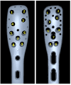
Plate screw hole numbers. The left plate is a Carbofix plate, the right plate the Philos plate. The left side of the image is anterior (1, 4, 5 and 8 are the anterior screw holes), right posterior (2, 3, 6 and 9 are the posterior screw holes).

Similar articles

References

    1. Gardner MJ, Weil Y, Barker JU, et al. The importance of medial support in locked plating of proximal humerus fractures. J Orthop Trauma 2007; 21: 185–191. - PubMed
    1. Helfen T, Siebenbürger G, Fleischhacker E, et al. Open reduction and internal fixation of displaced proximal humeral fractures. Does the surgeon’s experience have an impact on outcomes? PLoS One 2018; 13: e0207044. - PMC - PubMed
    1. Wang Q, Sheng N, Rui Bet al. et al. The neck-shaft angle is the key factor for the positioning of calcar screw when treating proximal humeral fractures with a locking plate. Bone Joint J 2020; 102-B: 1629–1635. - PMC - PubMed
    1. McMillan TE, Johnstone AJ. Primary screw perforation or subsequent screw cut-out following proximal humerus fracture fixation using locking plates: a review of causative factors and proposed solutions. Int Orthop 2018; 42: 1935–1942. - PubMed
    1. Omid R, Trasolini NA, Stone MAet al. et al. Principles of locking plate fixation of proximal humerus fractures. J Am Acad Orthop Surg 2021; 29: E523–E535. - PubMed

LinkOut - more resources