

Modular Hemipelvic Prosthesis Preserves Normal Biomechanics and Showed Good Compatibility: A Finite Element Analysis
- PMID: 39330251
- PMCID: PMC11433228
- DOI: 10.3390/jfb15090276
Modular Hemipelvic Prosthesis Preserves Normal Biomechanics and Showed Good Compatibility: A Finite Element Analysis
Abstract
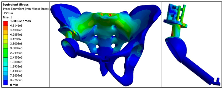
This study aimed to evaluate the biomechanical compatibility of a modular hemipelvic prosthesis by comparing stress distributions between an implanted pelvis and a healthy pelvis. Finite element analysis was used to simulate bilateral standing loads on both models, analyzing critical regions such as the sacroiliac joints, iliac crest, acetabulum, and prosthesis connection points. Six models with varied displacements of the hip joint rotational center were also introduced to assess the impact of deviations on stress distribution. The implanted pelvis had a stress distribution closely matching that of the intact pelvis, indicating that the prosthesis design maintained the biomechanical integrity of the pelvis. Stress patterns in displacement models with deviations of less than 10 mm were similar to the standard model, with only minor changes in stress magnitude. However, backward, upward, and inward deviations resulted in stress concentrations, particularly in the prosthesis connection points, increasing the likelihood of mechanical failure. The modular hemipelvic prosthesis demonstrated good biomechanical compatibility with minimal impact on pelvic stress distribution, even with moderate deviations in the hip joint's rotational center; outward, forward, and downward displacements are preferable to minimize stress concentration and prevent implant failure in cases where minor deviations in the rotational center are unavoidable during surgery.
Keywords: biomechanics; center of rotation; hemipelvic prosthesis; stress distribution; three-dimensional finite element.
Conflict of interest statement
The authors declare no conflicts of interest.
Figures


Similar articles
-
[Finite element analysis and static biomechanics of pelvic after modular hemipelvic prosthesis reconstruction].Sichuan Da Xue Xue Bao Yi Xue Ban. 2012 Mar;43(2):206-9. Sichuan Da Xue Xue Bao Yi Xue Ban. 2012. PMID: 22650032 Chinese.
-
Biomechanics study of a 3D printed sacroiliac joint fixed modular hemipelvic endoprosthesis.Clin Biomech (Bristol). 2020 Apr;74:87-95. doi: 10.1016/j.clinbiomech.2020.02.014. Epub 2020 Feb 28. Clin Biomech (Bristol). 2020. PMID: 32146381
-
Finite element analysis of the pelvis after modular hemipelvic endoprosthesis reconstruction.Int Orthop. 2013 Apr;37(4):653-8. doi: 10.1007/s00264-012-1756-6. Epub 2013 Jan 15. Int Orthop. 2013. PMID: 23318936 Free PMC article.
-
Modular hemipelvic endoprosthesis with a sacral hook: a finite element study.J Orthop Surg Res. 2019 Sep 11;14(1):309. doi: 10.1186/s13018-019-1338-z. J Orthop Surg Res. 2019. PMID: 31511034 Free PMC article.
-
A novel combined hemipelvic endoprosthesis for peri-acetabular tumours involving sacroiliac joint: a finite element study.Int Orthop. 2015 Nov;39(11):2253-9. doi: 10.1007/s00264-015-2891-7. Epub 2015 Jul 17. Int Orthop. 2015. PMID: 26183143
Cited by
-
Stress-Strain State Investigation and Ultimate Load on Femoral Implants Based on S-Type Ti6Al4V Titanium Alloy.J Funct Biomater. 2025 May 19;16(5):187. doi: 10.3390/jfb16050187. J Funct Biomater. 2025. PMID: 40422851 Free PMC article.
-
Clinical efficacy on the reconstruction of bone defects using modular hemipelvic prosthesis in patients with pelvic tumors.J Orthop Surg Res. 2024 Nov 30;19(1):812. doi: 10.1186/s13018-024-05282-x. J Orthop Surg Res. 2024. PMID: 39614373 Free PMC article.
-
Integrating finite element analysis in total hip arthroplasty for childhood hip disorders: Enhancing precision and outcomes.World J Orthop. 2025 Jan 18;16(1):98871. doi: 10.5312/wjo.v16.i1.98871. eCollection 2025 Jan 18. World J Orthop. 2025. PMID: 39850035 Free PMC article.
References
-
- Stegaroiu R., Kusakari H., Nishiyama S., Miyakawa O. Influence of prosthesis material on stress distribution in bone and implant: A 3-dimensional finite element analysis. Int. J. Oral. Maxillofac. Implants. 1998;13:781–790. - PubMed
Grants and funding
LinkOut - more resources
Full Text Sources
