. 2025 Feb 16;18(4):e202401484.
doi: 10.1002/cssc.202401484. Epub 2024 Nov 8.

Intensifying Cyclopentanone Synthesis from Furfural Using Supported Copper Catalysts

Affiliations

Intensifying Cyclopentanone Synthesis from Furfural Using Supported Copper Catalysts

Adarsh Patil et al. ChemSusChem. .

Abstract

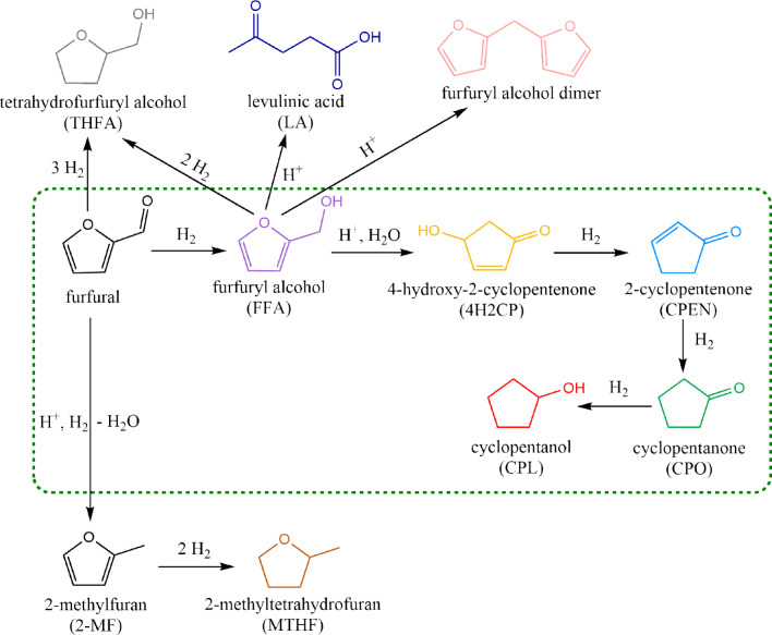
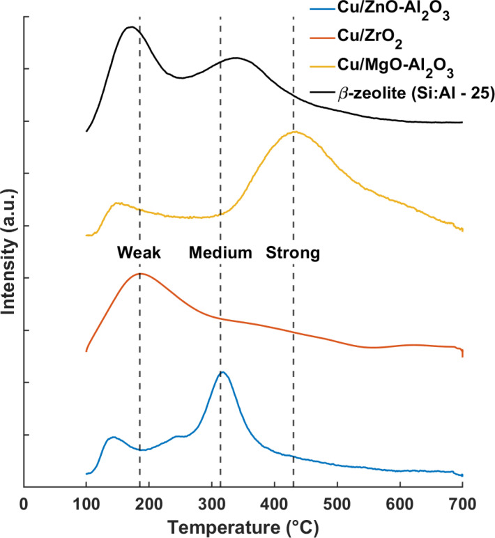
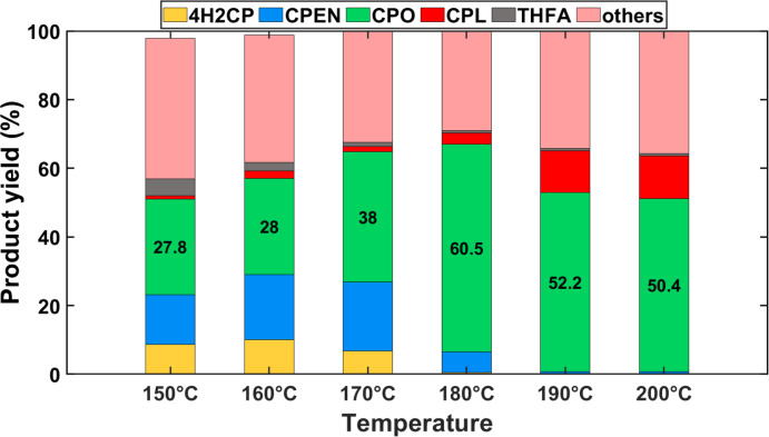
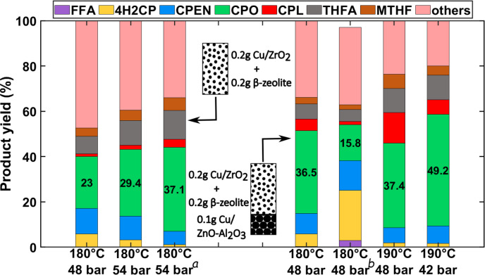
This work addresses catalytic strategies to intensify the synthesis of cyclopentanone, a bio-based platform chemical and a potential SAF precursor, via Cu-catalyzed furfural hydrogenation in aqueous media. When performed in a single step, using either uniform or staged catalytic bed configuration, high temperature and hydrogen pressures (180 °C and 38 bar) are necessary for maximum CPO yields (37 and 49 %, respectively). Parallel furanic ring hydrogenation of furfural and polymerisation of intermediates, namely furfuryl alcohol (FFA), limit CPO yields. Employing a two step configuration with optimal catalyst bed can curb this limitation. First, the furanic ring hydrogenation can be suppressed by using milder conditions (i. e., 150 °C and 7 bar, and 14 seconds of residence time). Second, FFA hydrogenation using tandem catalysis, i. e., a mix of β-zeolite and Cu/ZrO2, at 180 °C, 38 bar and 0.6, allows sufficient time for CPO formation and minimises polymerisation of FFA, thereby resulting in 60 % CPO yield. Therefore, this work recommends a split strategy to produce CPO from furfural. Such modularity may aid in addressing flexible market needs.

Keywords: Copper catalysis; Cyclopentanone; Furfural; Hydrogenation; Polymerization.


Conflict of interest statement

The authors have no conflict of interest to declare.

Figures

Figure 1
Figure 1
Reaction scheme for hydrogenation of furfural to CPO as collated from literature. The green box indicates the preferred reaction network of furfural hydrogenation to cyclopentanone.
Figure 2
Figure 2
NH3‐TPD of the different supported‐Cu catalysts.
Figure 3
Figure 3
Comparison of different supports on furfural hydrogenation to cyclopentanone using 1 wt.% furfural in water. Conditions: T=150–180 °C; Ptotal=12 bar; Wcat=1 gram; WSiC=3 gram; Qfeed=0.1 mL min−1, QH2=5 NmL min−1; and WHSV=0.06gfurfuralgcat-1hr-1 .
Figure 4
Figure 4
Effect of pressure on FFA hydrogenation to CPO using 1 wt.% FFA in water. Conditions: T=150 °C; Wcat=0.2 grams of Cu/ZrO2 and β‐zeolite each; WSiC=3.6 grams; Qfeed=0.2 mL min−1; QH2 =4 NmL min−1, WHSV=0.6 gFFAgcat-1h-1 .
Figure 5
Figure 5
Effect of temperature on FFA hydrogenation to CPO using 1 wt.% FFA in water. Conditions: T=150–200 °C; Ptotal=48 bar; Wcat=0.2 grams of Cu/ZrO2 and β‐zeolite each; WSiC=3.6 grams; Qfeed=0.2 mL min−1, QH2 =4 N, WHSV=0.6 gFFAgcat-1h-1 . Figures within the green bar indicate CPO yield.
Figure 6
Figure 6
Furfural hydrogenation to CPO using 1 wt.% furfural in water. The three stacked bars on the left‐hand side represent mixed Cu/ZrO2 and β‐zeolite bed while those on right‐hand side represent commercial Cu/ZnO‐Al2O3 before the mixed bed. Conditions: Temperature and pressure are indicated on the X‐axis. Wcat=indicated on the graph; Qfeed=0.2 mL min−1, QH2 =4 N, WHSV=0.06 and 0.4 gfurfuralgcat-1hr-1 for mixed and sequential bed, respectively. (a :Qfeed=0.15, QH2 =3 NmL min−1, b: Qfeed=0.4, QH2 =8 NmL min−1). Figures in the green bar indicate CPO yield for respective temperature.
Figure 7
Figure 7
FFA hydrogenation to CPO using 1 wt.% FFA in water. Conditions: T=180 °C; Ptotal=48 bar; Wcat=0.2 grams of Cu/ZrO2 and β‐zeolite each; WSiC=3.6 grams; Qfeed=0.2 mL min−1, QH2 =4 NmL min−1, WHSV=0.6 gFFAgcat-1h-1 .
Figure 8
Figure 8
XRD pattern of fresh vs. spent catalyst. Inset on the top right‐hand side shows an enlarged segment of XRD pattern in Cu0(111) region while the TEM images of fresh and spent catalysts are shown on the top left‐hand side.

References

    1. T. A. Werpy, J. E. Holladay, J. F. White 2004.
    1. Dunlop A. P., Ind. Eng. Chem. 1948, 40, 204–209.
    1. Ao L., Zhao W., Guan Y.-s., Wang D.-k., Liu K.-s., Guo T.-t., Fan X., Wei X.-y., RSC Adv. 2019, 9, 3661–3668. - PMC - PubMed
    1. J. H. Teles, B. Röβler, T. Genger, A. Glass, Method for the production of cyclopentanone 2010.
    1. Miki H., J. Jpn. Pet. Inst. 2019, 62, 282.

LinkOut - more resources